Setting Up Communication
SolarEdge Installation Guide – MAN-01-00002-1.6
76
4 An inverter has either RJ45/RJ11 connectors or block terminal connectors for
communication.
If the inverter has RJ45/RJ11 communication connectors, then connect as
follows:
• The RS485 bus uses a four-wire telephone cable and a six-wire RJ11
connecter (also known as RJ25). Insert the wire via one of the small
cable glands. The glands come from the factory pre sealed. Removal of
the sealing is required in order to insert the cable.
If a gland is opened and not used, be sure to reseal it. Otherwise, it may
affect the inverter’s functionality.
une glande est ouverte et non utilisée, assurez-vous de la refermer.
Sinon, cela pourrait affecter la fonctionnalité de l'onduleur.
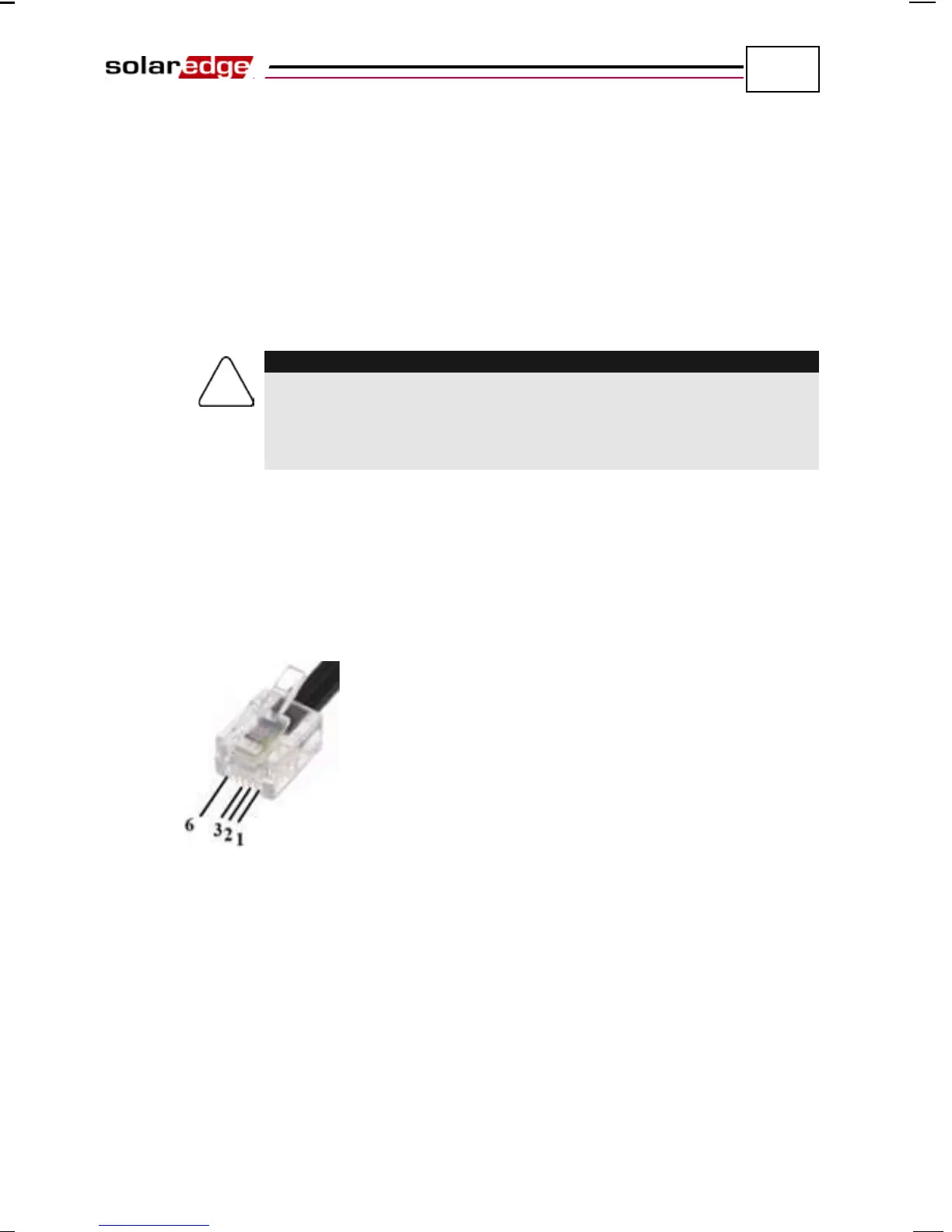
• After inserting the wire, crimp a connector using a standard telephone
wire crimper. Two pins (numbered 2 and 3) must be connected. The two
wires must both belong to the same twisted pair, which is usually
indicated by similarly colored wire. In addition, a grounding wire that is
connected to pin number 6 must also be connected. For this purpose, you
can use any remaining wire of the telephone cable. The wiring on the
next inverter should be the same.
Figure 43: Crimping the Wires
• Connect the RS485 cable connector to either of the RS485 plugs on
boards in the inverter.
• Connect the other end of the RS485 cable of the first inverter through the
gland to the RS485 connector on the board of the next inverter in the
chain, as described above.
• You can use both RS485 connectors to wire up to two inverters – one to
the left and one to the right