Setting Up Communication
SolarEdge Installation Guide – MAN-01-00002-1.6
80
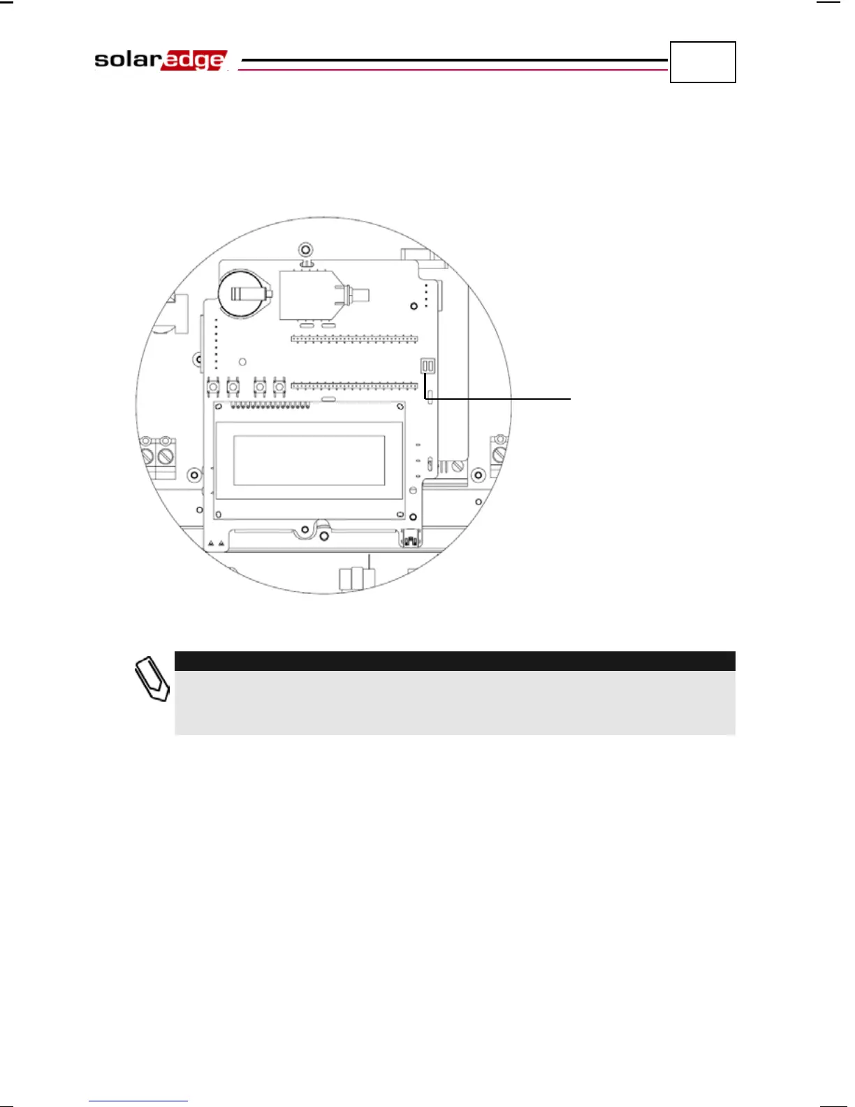
4 The two inverters at the ends of the chain (meaning the first inverter and the
last inverter) must be terminated by switching a termination dip-switch inside
the inverter to ON. The switch is marked SW6 and it is the switch closest to
the ESC button, as shown below:
Figure 47: RS485 Termination Switch
:
Only the two inverters at the end
s of the chain should be terminated for best
performance. The other inverters in the chain should have the termination switch
OFF.
5 Choose a single inverter to be the connection point between the RS485 bus
and the SolarEdge Monitoring Server.
6 Connect the Master, as described above, to the SolarEdge Monitoring Server
via either Ethernet, as described in the Creating an Ethernet (LAN)
Connection section on page 70, or RS232, as described in the Creating an
RS232 (UART) Connection section on page 69.