6-6
BVM-D32E1WA/D32E1WE/D32E1WU
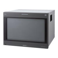
CRT
LCC TOP LEFT LCC TOP RIGHT
LCC BOTTOM LEFT LCC BOTTOM RIGHT
NS Coil
(Beam landing correction when viewed from the CRT side)
7. Beam Landing Correction Circuit
This monitor has the five beam landing correction coils (referred to as LCC = Landing Correction Coil
and NS Coil = North South Coil) around the CRT as shown. The optimum beam landing is maintained
by flowing the appropriate correction currents through these coils. The following items are corrected by
the beam landing correction.
1. Correction of the beam landing that changes in accordance with the direction (horizontal terrestrial
magnetism) in which the monitor is installed. The vertical terrestrial magnetism is corrected by the
purity magnets that are placed inside the monitor.
2. Correction of the beam landing that changes in accordance with the change of ambient temperature.
3. Correction of the beam landing that changes in accordance with the change of the average beam
current.
4. Correction of the beam landing characteristics of the CRT.
5. Correction of the beam landing that changes in accordance with the partial change of surrounding
magnetic field.
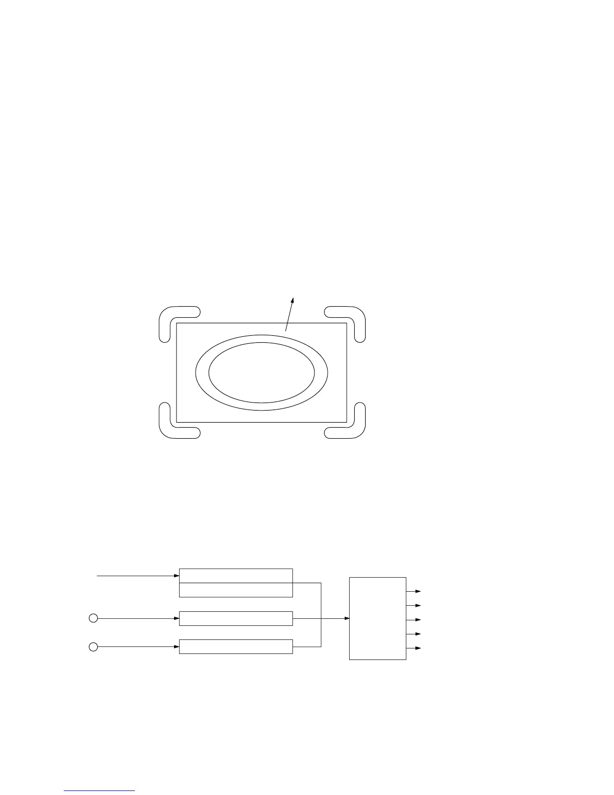
Basic structure of the correction circuit is shown below. The respective blocks are described one after
another.
Direction correction data
Direction correction signal
Partial correction signal
Ambient temperature correction signal
Temperature sensor
Beam current correction signal
ABL signal
LCC drive
NS coil
LCC coil
LCC coil
LCC coil
LCC coil