6-7
BVM-D32E1WA/D32E1WE/D32E1WU
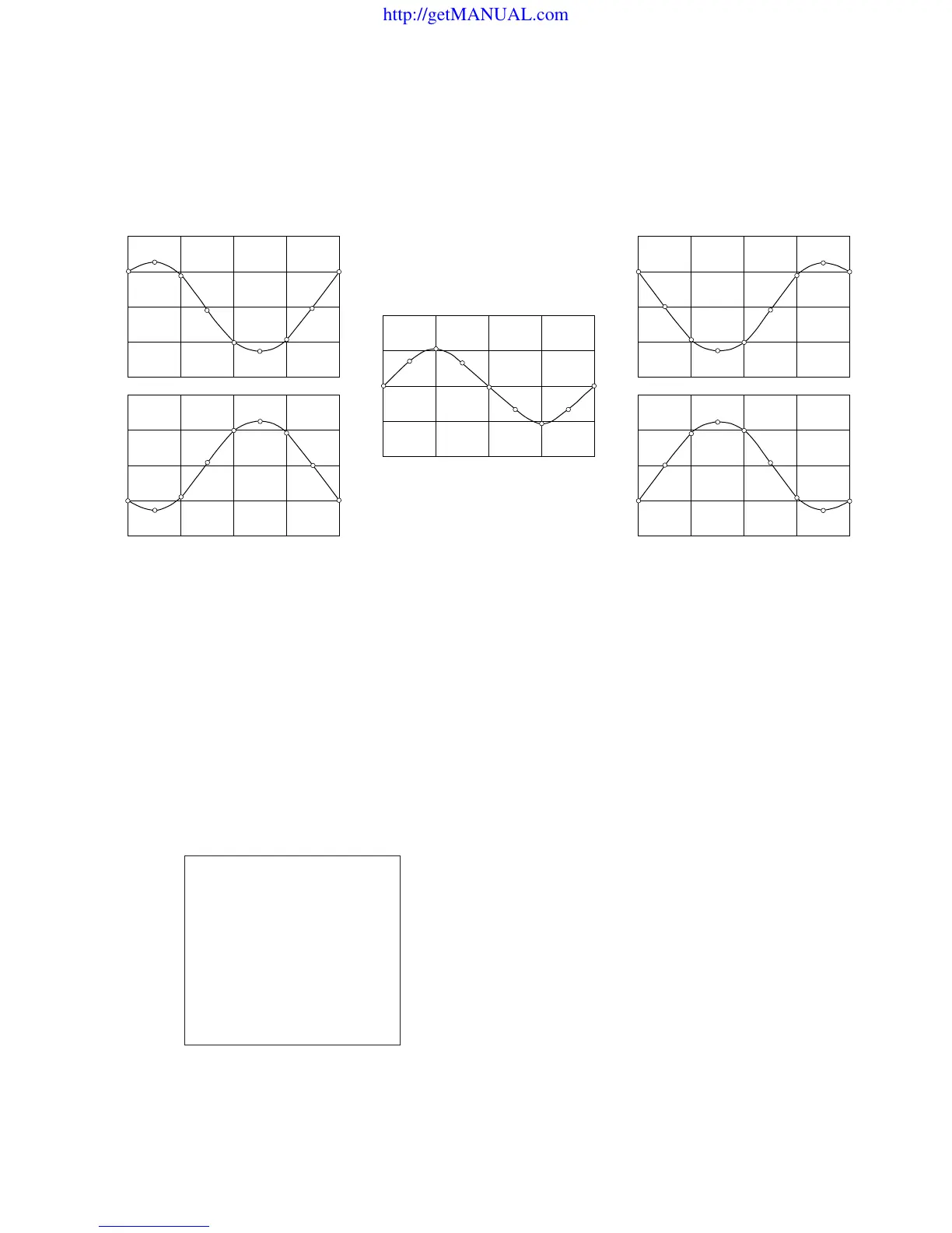
Direction correction signal
State of beam landing is affected by the direction in which the monitor is installed. The change of beam landing can be
corrected by flowing the sinusoidal current through the five correction coils as show below.
ESWNE
LCC TOP LEFT
ESWNE
NC Coil
ESWNE
LCC TOP RIGHT
ESWNE
LCC BOTTOM LEFT
ESWNE
LCC BOTTOM RIGHT
MANUAL
DIRECTION
FINE ADJUST
NS
TOP LEFT
TOP RIGHT
BOTTOM LEFT
BOTTOM RIGHT
RESET
EAST
100
100
100
100
100
100
MENU/SET UP/WHITE UNIFORMITY (1/2)
MANUAL
In this monitor, the eight different direction correction currents as shown above corresponding to the eight
terrestrial directions are stored as the pattern data in the internal memory so that an appropriate pattern
that corresponds to the installation direction, can be called.
The pattern that is called from the internal memory, is sent from the microprocessor of the monitor to
IC711 where the digital correction data is D/A converted. The DC output signal from the D/A converter
is added in the LCC drive block.
The menu for landing correction is shown. The landing
pattern that corresponds to the terrestrial direction can be
called from the DIRECTION item of the menu. Any
desired pattern can be selected from the following eight
patterns.
NORTH, NORTH EAST
EAST, SOUTH EAST
SOUTH, SOUTH WEST
WEST, NORTH WEST
Select an appropriate direction from the eight patterns that
provides most uniform landing over the entire screen.
Menu for landing correction.
http://getMANUAL.com