6-8
BVM-D32E1WA/D32E1WE/D32E1WU
Partial correction signal
Some beam landing cannot be corrected by the direction correction alone in some cases depending on the
installation environment of the monitor. The partial correction is used for fine adjustment in such a case
as described above. The five registers are prepared for the five coils (NS, TOP LEFT, TOP RIGHT,
BOTTOM LEFT and ABOTTOM RIGHT) for the FINE adjustment, that can be selected by the landing
correction menu as described in the previous paragraph. The beam landing can be finely adjusted by
adjusting these coils.
The data that prepared by these coils for fine adjustment by the MENU, is sent to IC711 in the same way
and is added in the LCC drive block.
- About Automatic Adjustment of Direction Correction and Partial Correction -
In this monitor, the direction correction and the partial correction can be automatically performed using
the option probe (BKM-14L) as follows.
Select AUTO using the MENU (MENU/SET UP/WHITE UNIFORMITY (1/2)). Connect the option
probe (BKM-14L) and start the automatic adjustment. The optimum directional correction data and the
optimum partial correction data can be automatically calculated and set in the monitor based on the
luminance value on the CRT that is measured by the optional probe. The direction correction and the
partial correction are sent to IC711 in the same way as in the MANUAL adjustment mode to drive the
correction circuit.
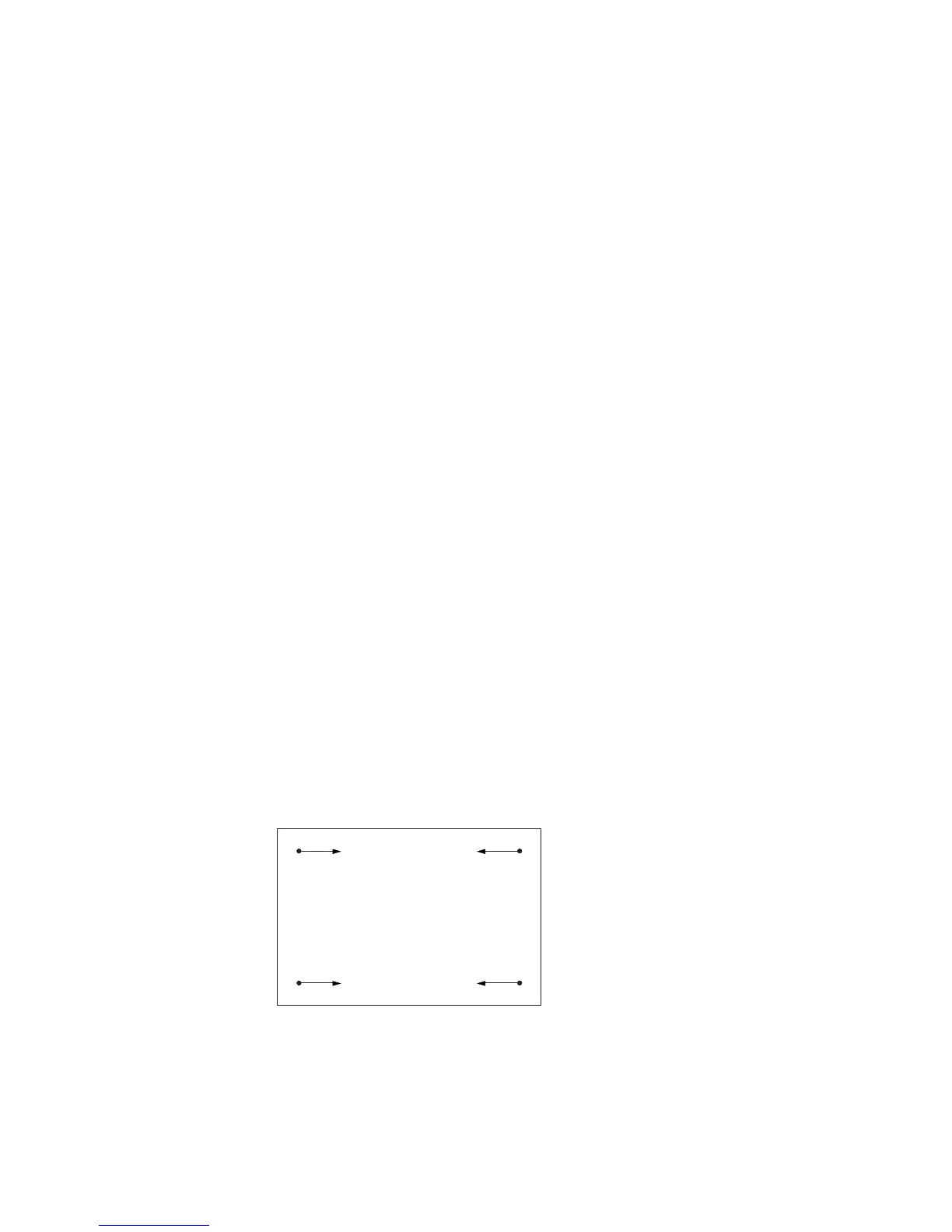
Ambient temperature correction signal
As the ambient temperature of the monitor increases, the beam landing changes in the directions as shown
in the illustration. It is assumed that amount of the beam landing change is linear with respect to the
change of ambient temperature. Then the correction signal that changes linearly with the change of
ambient temperature, is created and is added to the LCC drive at the four corners of CRT. The tempera-
ture sensor the diode D600 that detects temperature using the temperature characteristics of the diode.
The detected temperature signal is the DC voltage that is outputted from IC605 pin-7 and added at the
LCC drive block.
Because the temperature sensor diode D600 is located in the PA board, not only the ambient temperature
change but also the temperature inside the monitor is also detected so that difference between the detected
temperature and the ambient temperature is created. The circuit that is prepared to cancel the difference
is connected to IC622 pin-5.
Directions of the landing change when the ambient temperature increases.
(Directions are inverted when the ambient temperature decreases.)
CRT screen