5-32
Address
00 to 0F
10
11
12
13
14
15
16
17
18
19
1A
1B
1C
1D
1E
1F
20
21
22
23
24
25
26
27
28
29
2A
2B
2C
2D
2E
2F
30
31
32
33
34
35
36
37
38
39
3A
3B
3C
3D
3E
3F
40
41
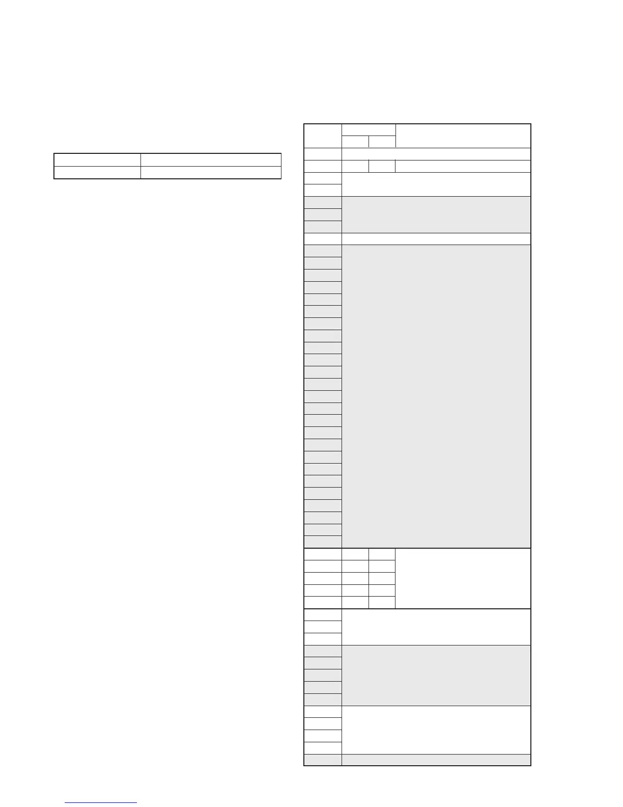
Initial value
NTSC
00
88
8D
A8
BD
C8
PAL
00
88
8D
A8
BD
C8
Remark
Test mode
Fixed data-1
(Initialized data)
Fixed data-2
(Modified data, copy the data built in
the same model.)
Fixed data-1
Fixed data-2
(Modified data, copy the data built in
the same model.)
Battery down adj.
Fixed data-1
Fixed data-2
Fixed data-1
Fixed data-2
4. Initializing the D Page Data
Note: If the page D data is initialized, the following adjustments must be
performed again.
1) Modification of D page data
2) “Base Band Block Adjustment” of the video system adjustments
3) LCD system adjustments
4) Color electronic viewfinder system adjustments
5) Battery end adjustment
Adjusting page D
Adjusting Address 10 to 8F
Initializing Method:
1) Select page: 0, address: 01, and set data: 01.
2) Select page: 3, address: 80, set data: 0D, and press the PAUSE
button of the adjustment remote commander.
3) Select page: 3, address: 80, and check that the data is “1D”.
4) Perform “Modification of D Page Data”.
5. Modification of D Page Data
If the D page data has been initialized, change the data of the “Fixed
data-2” address shown in the following table by manual input.
Modifying Method:
1) Before changing the data, select page: 0, address: 01, and set
data: 01.
2) New data for changing are not shown in the tables because
they are different in destination. When changing the data, copy
the data built in the same model.
Note: If copy the data built in the different model, the camcorder may
not operate.
3) When changing the data, press the PAUSE button of the
adjustment remote commander each time when setting new
data to write the data in the non-volatile memory.
4) Check that the data of adjustment addresses is the initial value.
If not, change the data to the initial value.
Processing After Modifying Data
1) Select page: 2, address: 00, set data: 29, and press the PAUSE
button of the adjustment remote commander.
2) Select page: 2, address: 01, set data: 29, and press the PAUSE
button of the adjustment remote commander.
3) Perform the following adjustments.
• “Base Band Block Adjustments” of the video system
adjustments
• LCD system adjustments
• Color electronic viewfinder system adjustments
• Battery end adjustment
6. D Page Table
Note: Fixed data-1 : Initialized data. ( Refer to “4. Initializing the C Page
Data”.)
Fixed data-2 : Modified data. (Refer to “5. Modification of C Page
Data”.)