2-1
DCR-PC1/PC1E
SECTION 2
DISASSEMBLY
NOTE: Follow the disassembly procedure in the numerical order given.
The following flow chart shows the disassembly procedure.
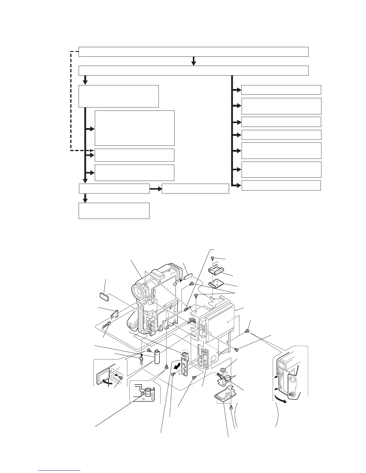
2-1. CABINET (L) ASSEMBLY, CABINET (R) ASSEMBLY
V
C
-2
1
0
B
o
a
rd
DD-111
Board
@§
Cabinet (L) assembly
(Refer to sec. 2-2.)
@∞
Cabinet (R) assembly
(Refer to sec. 2-5.)
@º
Control switch block
(ME-4780)
(VC-210 board CN2202)
@¢
Remote control
window assembly
@™
Harness
(PD-107)
(VC-210 board CN2908)
@£
Harness (PR-61)
(VC-210 board CN2201)
5
Harness (LI-58)
(MR-40 board CN2507)
!º
Open the LCD and
remove the screw.
(0-No. +P2 M1.7)
!¡
Hinge cover
!§
Two screws
(0-No. +P2 M1.7)
!™
Open the
DV jack
cover
assembly.
!∞
Screw (0-No. +P2 M1.7)
!¶
Two screws
(0-No. +P2 M1.7)
4
Two screws
(+K M2
×
3.5 with 3 locks)
1
Two screws
(+K M2
×
3.5 with 3 locks)
!ª
Two screws
(0-No. +P2 M1.7)
!ª
Two screws
(0-No. +P2 M1.7)
!•
Open the cassette
lid by sliding the
EJECT knob in the
direction of the arrow.
9
Secondary
lithium batteries
(2 pcs)
6
Tripod screw
8
Remove the
two solderings.
7
FP-36 flexible
board
2
Accessory shoe
3
Shoe plate
!£
Two screws
(0-No. +P2 M1.7)
The FP-36 flexible
board is attached
on the tripod screw
by both sided
adhesive tape.
Remove
the claw.
!¢
Remove the claw of the jack ornamental
plate and remove it in the direction shown by the arrow.
@¡
Harness (SP-158)
(DD-111 board CN9900)
The cabinet
(L) when viewed
from the bottom.
2-1. CABINET (L) ASSEMBLY, CABINET (R) ASSEMBLY
1
-
7
DD-111 board,
Battery terminal
8
-
!•
MR-40 board
!ª
,
@º
VC-210 board
@¡
-
@∞
MD block
1
-
6
MD block assembly
7
,
8
EVF assembly
9
-
!£
Microrophone unit
1
-
8
Grip belt
9
-
!ª
Control switch block
@º
-
#º
Cabinet (G)
1
VF lens assembly
2
-
6
CD-203 board
7
-
!¡
Lens device
1
-
@¡
PD-102 board
1
-
6
,
@™
-
@•
LCD hinge assembly
@ª
-
#™
Speaker
#£
DV jack cover
#¢
,
#∞
S-terminal cover assembly
#§
Control switch block
(ME-4780)
1
-
!£
VF-125 board
#¶
-
$¡
LCD block
DCR-PC1
2-2.
2-3.
2-4.
2-4.
2-6.
2-6.
2-7.
2-5.
2-5.
2-5.
2-5.
2-5.
2-5.
2-5.