2-4
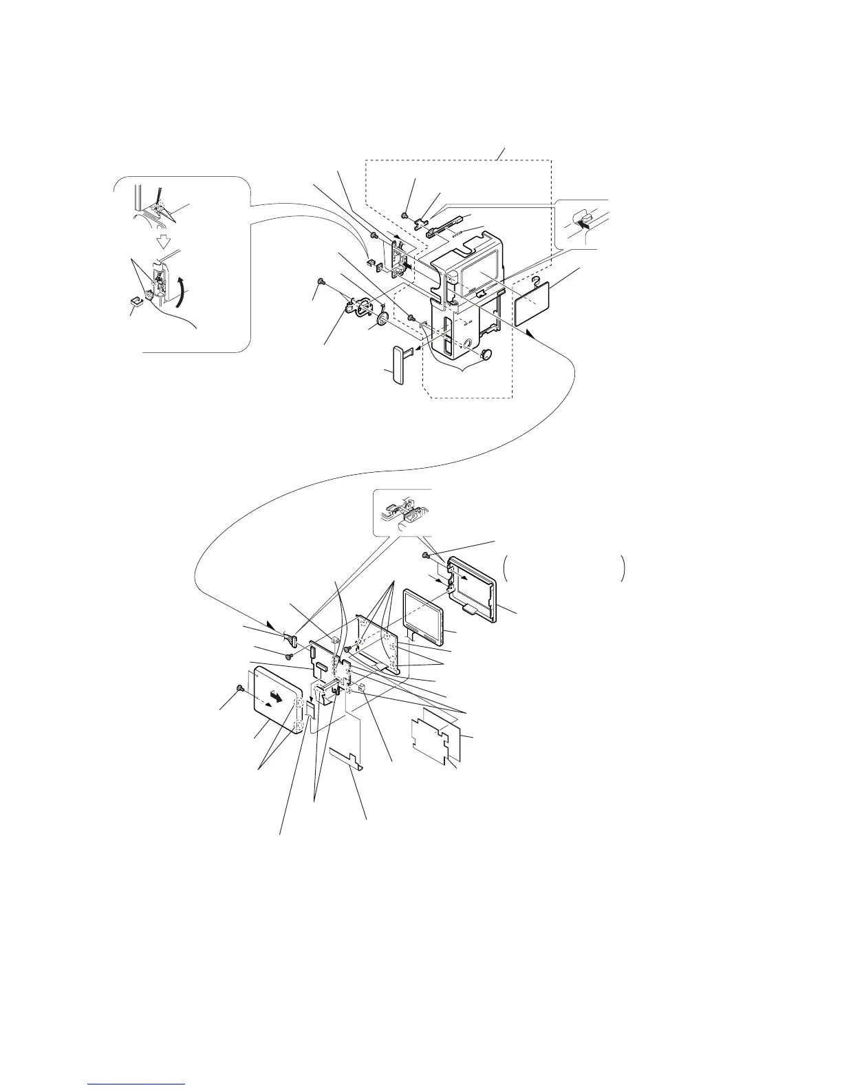
2-5. CABINET (R) ASSEMBLY, PD-102 BOARD
PD-102
BOARD
a
b
b
a
@£
LCD hinge assembly
Cabinet (R) assembly
#£
DV jack cover assembly
#∞
S-terminal
cover assembly
@™
Two screws
(M1.7)
4
Two screws
(0-No. +P2 M1.7)
9
Screw (0-No. +P2 M1.7)
8
Screw
(0-No. +P2 M1.7)
6
Harness (PD-107)
1
Two screws
(0-No. +P2 M1.7)
2
Disengage the claws by
moving it in the direction
of arrow
a
.
!•
PD-102 board
#¢
Screw (M1.7)
@ª
Two screws
(M1.7)
#º
Speaker retainer
@¢
Remove the
claw with
tweezers or
the like.
@∞
Close the
LCD.
@¶
Remove
the soldering
@§
SW clip
@•
PR-31 board
#™
Harness (SP-158)
#¡
Speaker
(2.0 cm)
#•
LCD lock pin
$º
LCD lock
$¡
Compres-
sion coil
spring
#¶
Push the area
shown by the
arrow.
#§
Control switch
block (ME-4780)
!™
LCD cabinet (L)
3
LCD cabinet (R)
!º
LCD
!¢
Cold cathode florescent tube
@¡
BL shielding sheet
!ª
BL insulation sheet
@º
PD insulation sheet
!¶
Inverter transformer unit
!£
Remove
the claws.
!§
PCB clip
!§
PCB clip
!£
Remove the claws.
!™
Remove the claws.
!¡
Remove
soldering.
!∞
Remove the solderings.
#ª
LCD lock retainer
Rotate the LCD cabinet
assembly by 90 degrees
and remove the screws.
a
5
Remove the rotary axis of the
LCD hinge assembly and the
LCD cabinet (L).
7
Connector (PD-102 board CN8200)