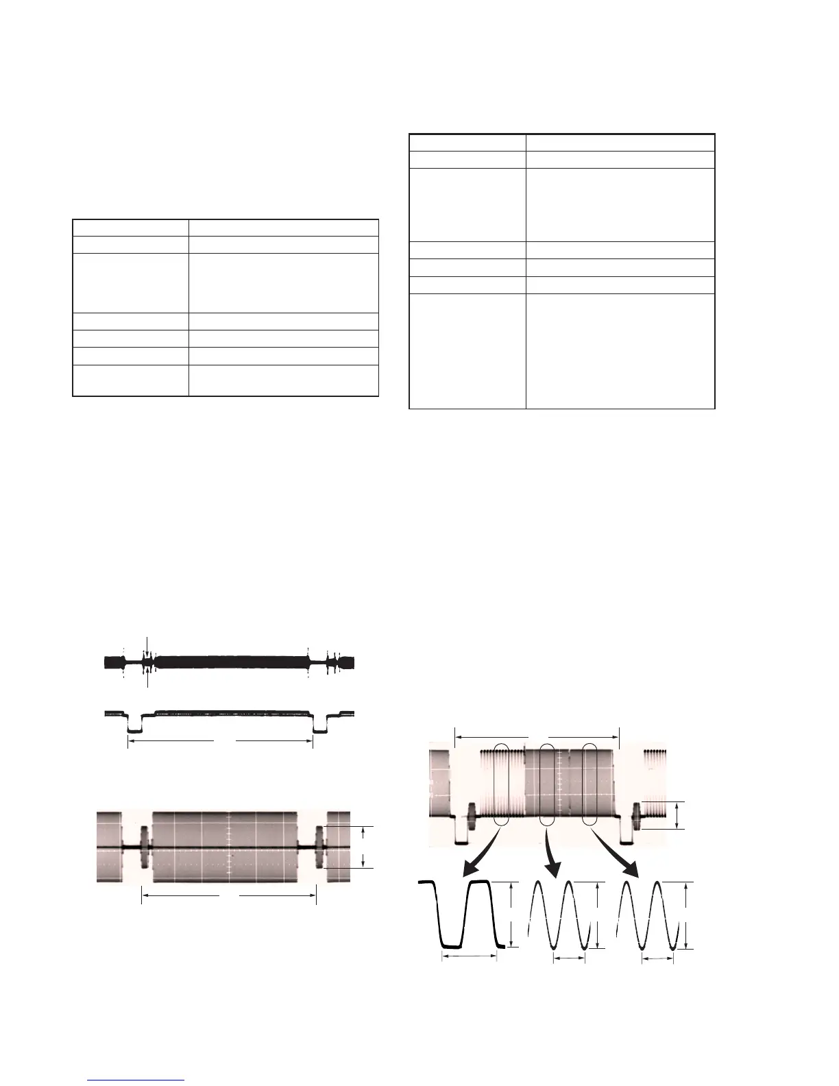
5-38
3-5. VIDEO SYSTEM ADJUSTMENTS
Before perform the video system adjustments, check that the
specified value of “36 MHz Master Oscillator Adjustment” of
“CAMERA SYSTEM ADJUSTMENT” is satisfied.
3-5-1. Base Band Block Adjustments
1. Chroma BPF f0 Adjustment (VC-210 board)
Set the center frequency of IC1402 chroma band-pass filter.
Mode VTR stop
Signal No signal
Measurement Point CH1: Chroma signal terminal of
S-VIDEO jack (terminated in 75 Ω)
CH2: Y signal terminal of S-VIDEO
jack (terminated in 75 Ω)
Measuring Instrument Oscilloscope
Adjustment Page C
Adjustment Address 2B
Specified Value A = 100 mV p-p or less
B = 200 mV p-p or more
Adjusting Method:
1) Check that the burst signal (B) is output to the chroma signal
terminal of S-VIDEO.
2) Select page: 0, address: 01, and set data: 01.
3) Select page: 3, address: 0C, set data: 04, and press the PAUSE
button of adjustment remote commander.
4) Change the data of page: C, address: 2B for the minimum
amplitude of the burst signal level (A).
5) Press the PAUSE button of the adjustment remote commander.
6) Select page: 3, address: 0C, set data: 00, and press the PAUSE
button of adjustment remote commander.
7) Check that the burst signal level (B) fulfills the specified value.
8) Select page: 0, address: 01, and set data: 00.
When the data of page: 3, address: 0C, is 04:
Fig. 5-3-3
When the data of page: 3, address: 0C, is 00.
Fig. 5-3-4
CH1
CH2
A
H
H
CH1 B
2. Line Output Y, Cr, Cb Level Adjustment
(VC-210 board)
Mode Camera
Subject Arbitrary
Measurement Point Y level : Y signal terminal of
S VIDEO jack (terminated in 75 Ω)
Cr, Cb, burst level : Video terminal of
AUDIO/VIDEO jack (terminated in
75 Ω)
Measuring Instrument Oscilloscope
Adjustment Page C
Adjustment Address 25, 26, 27
Specified Value Y level: A = 714 ± 14 mV (NTSC)
A = 700 ± 14 mV (PAL)
Cr level: B = 714 ± 14 mV (NTSC)
B = 700 ± 14 mV (PAL)
Cb level: C = 714 ± 14 mV (NTSC)
C = 700 ± 14 mV (PAL)
Burst level:D = 286 ± 14 mV (NTSC)
D = 300 ± 6 mV (PAL)
Adjusting Method:
1) Select page: 0, address: 01, and set data: 01.
2) Select page: 2, address: 35. After noting down the data of this
address, set data: 01 to this address.
3) Select page: 3, address: 0C, set data: 02, and press the PAUSE
button of adjustment remote commander.
4) Select page: C, address: 25, and change the data until the Y
signal level (A) is adjusted to the specified value.
5) Press the PAUSE button of the adjustment remote commander.
6) Select page: C, address: 26, and change the data until the Cr
signal level (B) is adjusted to the specified value.
7) Press the PAUSE button of the adjustment remote commander.
8) Select page: C, address: 27, and change the data until the Cb
signal level (C) is adjusted to the specified value.
9) Press the PAUSE button of the adjustment remote commander.
10) Check that the burst signal level (D) has the specified value.
11) Select page: 3, address: 0C, set data: 00, and press the PAUSE
button of adjustment remote commander.
12) Select page: 2, address: 35, and set data that is noted down at
step 2).
13) Select page: 0, address: 01, and set data: 00.
Fig. 5-3-5
H
D
A
1.2
µ
sec
B
0.28
µ
sec (NTSC)
0.23
µ
sec (PAL)
C
0.28
µ
sec (NTSC)
0.23
µ
sec (PAL)