5-34
Fig. 5-3-3
3-3. SYSTEM CONTROL SYSTEM ADJUSTMENT
1. Battery End Adjustment (VC-210 board)
Set the battery end voltage.
If the voltage is incorrect, the life of the battery will shorten. The
image at the battery end will also lose synchronization.
Mode Camera recordings
Subject Arbitrary
Measurement Point Display data of page: 2, address: 5D
Measuring Instrument Adjustment remote commander
Adjustment Page D
Adjustment Address 30 to 34
Switch setting:
1) AUTO FOCUS .................................................................OFF
2) LCD display ................................................................. Closed
3) View finder ............................. ON (View finder is pulled out)
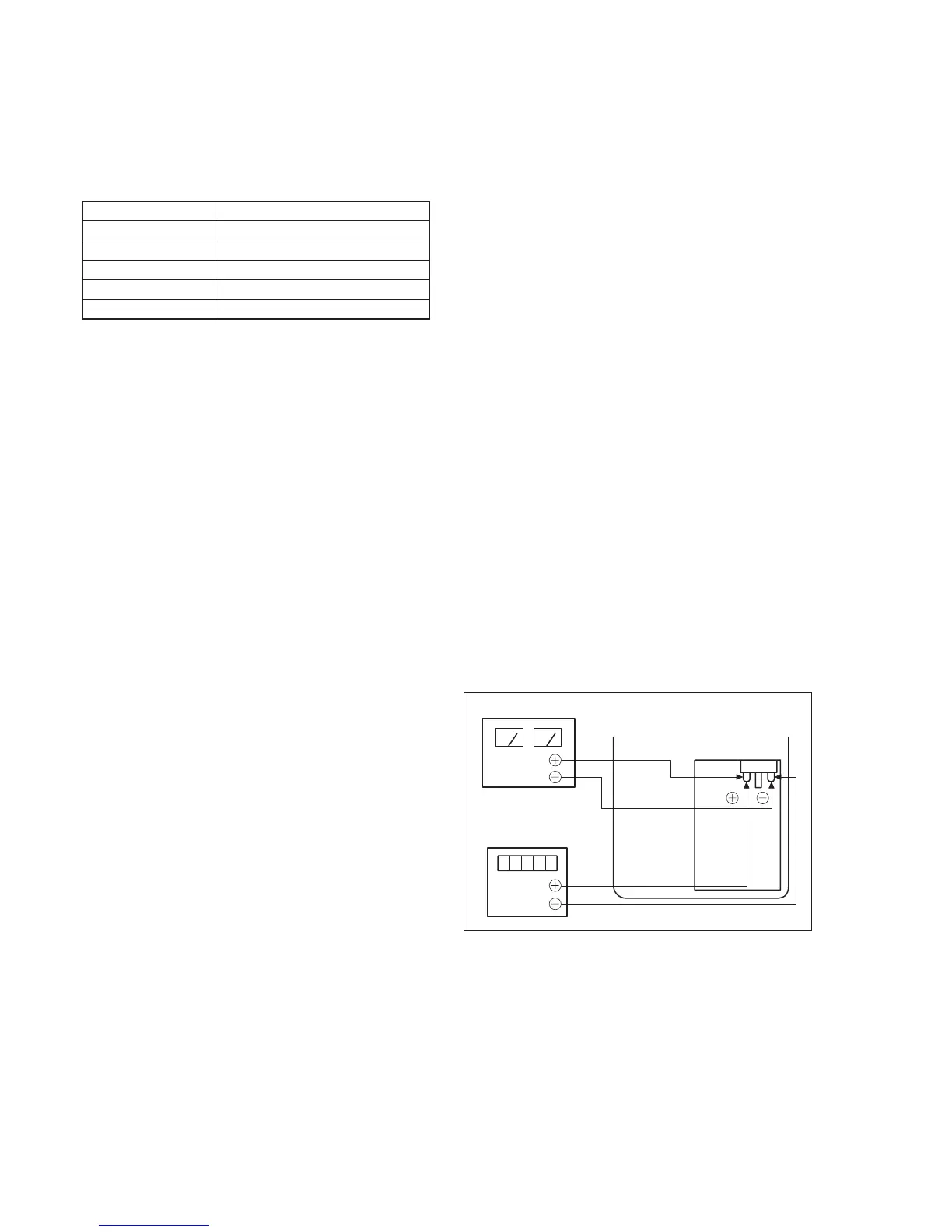
Connection:
1) Connect the regulated power supply and the digital voltmeter
to the battery terminal as shown in Fig. 5-3-3.
Adjusting method:
1) Adjust the output voltage of the regulated power supply so that
the digital voltmeter reading is 3.5 ± 0.1 V dc.
2) Turn off the power supply.
3) Turn on the HOLD switch of the adjustment remote
commander.
4) Turn on the power supply.
5) Load a cassette, and set the recording mode.
6) Select page: 0, address: 01, and set data: 01.
7) Decrease the output voltage of the regulated power supply so
that the digital voltmeter reading is 3.30 ± 0.01 V dc.
8) Select page: 2, address: 5D, read the data, and this data is named
Dref.
9) Set the read-out data (Dref) to page: D. address: 30 and press
the PAUSE button.
10) Convert Dref to decimal notation, and obtain Dref'. (Refer to
Table 5-4-1 “Hexadecimal-decimal Conversion Table” of “5-
4. Service Mode”.)
11) Calculate D31', D32', D33', D34' and D49' using following equations
(decimal calculation), convert it to a hexadecimal number, and
input each adjustment address.
Address: 31 D31' = Dref' + 3
Address: 32 D32' = Dref' + 10
Address: 33 D33' = Dref' + 10
Address: 34 D34' = Dref' + 10
Address: 49 D49' = Dref' + 13
Note: After setting each data, be sure to press the PAUSE button of
the adjustment remote commander.
12) Select page: 0, address: 01, and set data: 00.
Regulated power supply
3.30
±
0.01 Vdc
Battery terminal
Digital voltmeter