2-3
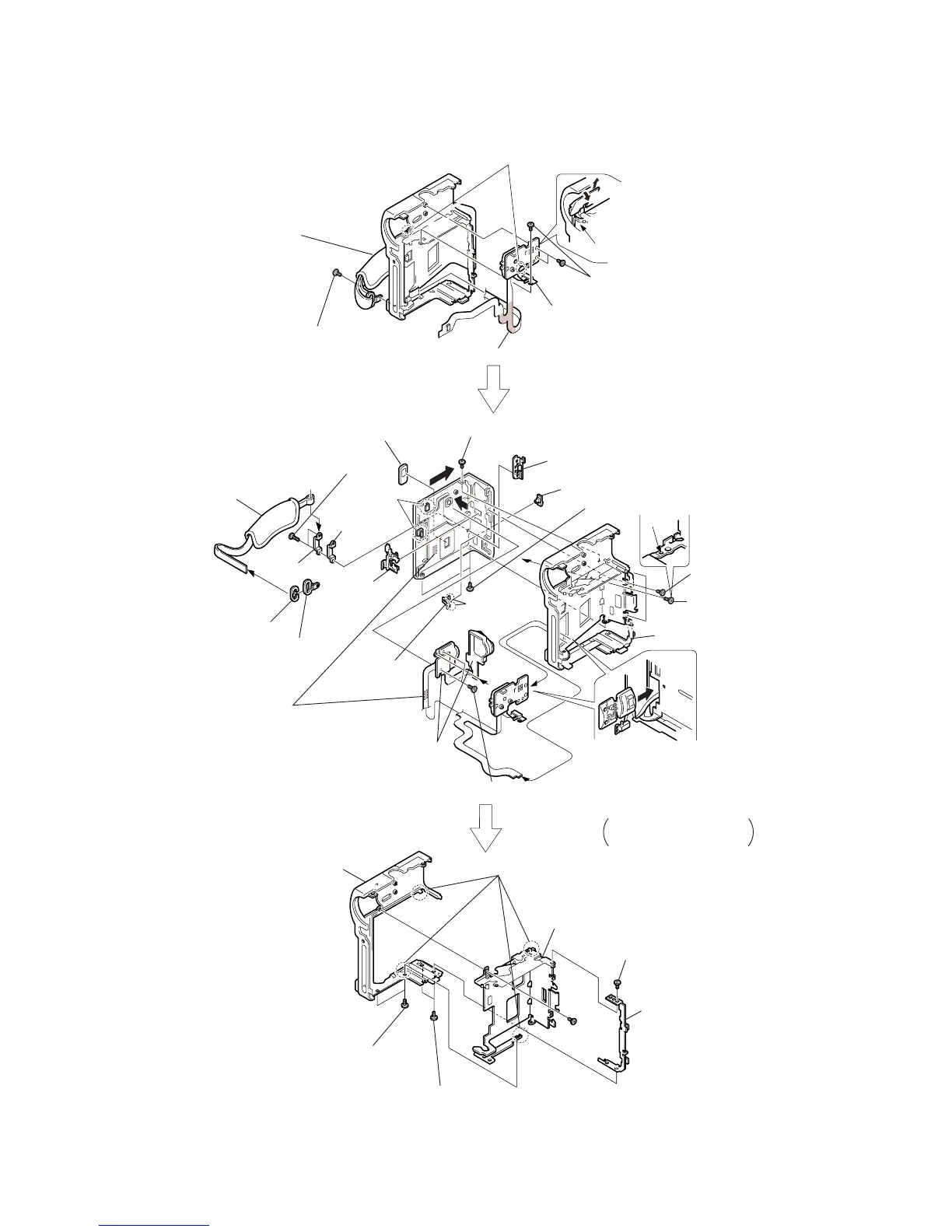
2-4. CONTROL SWITCH BLOCK
a
a
2
Remove an end of the grip belt.
9
Remove the area that is adhered, shown by hatching.
!•
Remove the area
that is adhered,
shown by hatching.
@¢
Cassette compartment window
Be sure to disengage the catch.
Be sure to disengage the catch.
Control switch block
Slant here in the direction of the
arrow
a
and remove it in the
direction of the arrow
b
.
1
Screw (0-No. +P2 M2.0)
4
Grip belt
7
Strap bracket
8
Bracket cap
5
Bracket cover
6
Belt bracket
!º
Two screws
(0-No. +P2 M1.7)
!£
Screw (0-No. +P2 M1.7)
!£
Three screws
(0-No. +P2 M1.7)
!™
Screw
(0-No. +P2 M1.7)
!£
Two screws (0-No. +P2 M1.7)
!¶
Two screws (0-No. +P2 M1.7)
@§
Two screws (0-No. +P2 M1.7)
@•
Two screws (0-No. +P2 M1.7)
@§
Screw (0-No. +P2 M1.7)
@¶
Lock board
#º
Cabinet (G)
#¡
Cabinet (L)
Cabinet (L) assembly
!§
Close the door of the grip lock
assembly once and remove the
control switch that is attached
to the cabinet (L), from the
cabinet (L) as shown.
@™
G lock slider
!ª
Control switch
block (FK-4780)
@º
FADER
button
!∞
Metal sheet nut
@£
EJECT knob
b
a
d
c
!¡
!¢
Remove the
claws.
@¡
Remove
the claws.
@ª
Remove the claws.
Be careful that the flexible
board is not caught.
@∞
3
Two screws
(0-No. +P2 M2)