5-28
3-1-4. Connecting the Equipment
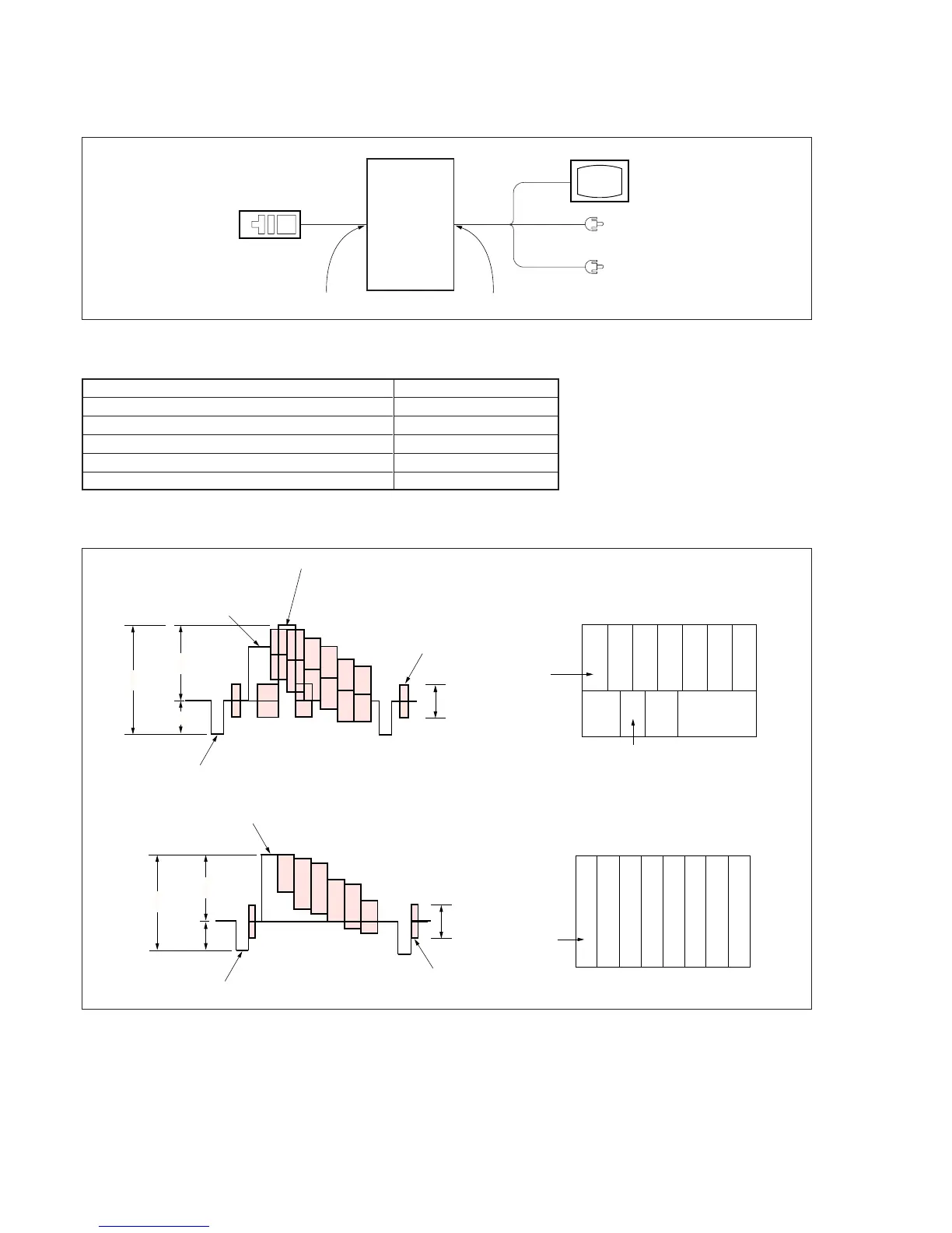
Connect the measuring instruments as shown in Fig. 5-3-1, and perform the adjustments.
Fig. 5-3-1
Adjustment
remote
commander
LANC jack
Main unit
AUDIO/VIDEO/HEADPHONES termina
Monitor TV
VIDEO
(Yellow)
AUDIO L (White)
AUDIO R (Red)
3-1-5. Alignment Tapes
Use the alignment tapes shown in the following table.
Fig. 5-3-2 shows the 75% color bar signals recorded on the alignment tape for Audio Operation Check.
Note: Measure with video terminal (Terminated at 75 Ω)
1V
0.714V
0.286V
White (75%)
White (100%)
Yellow
Cyan
Green
Magenta
Red
Blue
Burst signal
0.286V
Q
I
Horizontal sync signal
(75%)
White
Yellow
Cyan
Green
Magenta
Red
Blue
Q
I
White
(100%)
Black
Color bar signal waveform Color bar pattern
Fig. 5-3-2
3-1-6. Output Level and Impedance
Video output
Special stereo mini jack
Output signal: 1 Vp-p, 75 Ω unbalanced,
sync negative
S video output
4-pin mini DIN
Luminance signal: 1 Vp-p, 75 Ω unbalanced,
sync negative
Chrominance signal: 0.286 Vp-p, 75 Ω unbalanced (NTSC)
0.300 Vp-p, 75 Ω unbalanced (PAL)
Use
Tape path adjustment
Switching position adjustment
Audio system adjustment
Operation check
BIST check
Name
Tracking standard (XH2-1)
SW/OL standard (XH2-3)
Audio operation check (XH5-3 (NTSC), XH5-3P (PAL))
System operation check
(XH5-5 (NTSC), XH-5-5P (PAL))
BIST check (XH5-6 (NTSC), XH5-6P (PAL))
1V
0.7V
0.3V
White (100%)
Yellow
Cyan
Green
Magenta
Red
Blue
Burst signal
Horizontal sync signal
0.3V
(100%)
Yellow
Cyan
Green
Magenta
Red
Blue
White
Black
Audio output
Special stereo mini jack
Output level: 327 mV (at load impedance 47 kΩ)
Output impedance: Below 2.2 kΩ
Color bar signal waveform
Color bar pattern
For NTSC model
For PAL model