5-21
1-5. LCD SYSTEM ADJUSTMENT
Note 1: The back light (fluorescent tube) is driven by a high voltage AC
power supply. Therefore, do not touch the back light holder to
avoid electrical shock.
Note 2: When replacing the LCD unit, be careful to prevent damages
caused by static electricity.
Note 3: Adjust the LCD BRIGHT button to its center of adjustment range.
Note 4: Set the LCD COLOR to its center of adjustment range from the
menu display.
[Adjusting connector]
Most of the measuring points for adjusting the LCD display are
concentrated in CN8201 of the PD-102 board.
The following table shows the pin numbers and signal name of
CN8201.
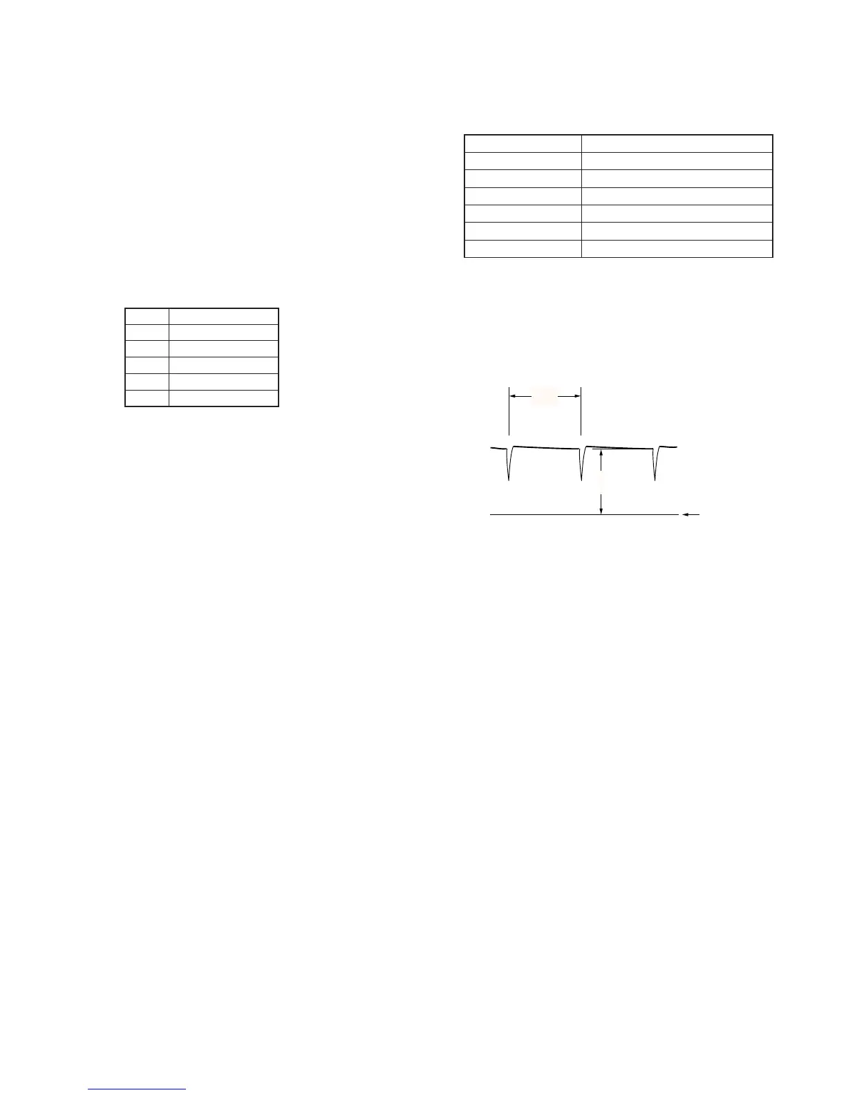
1. VCO Adjustment (PD-102 board)
Set the VCO free-run frequency. If deviated, the LCD display will
be blurred.
Mode VTR stop
Signal No signal
Measuring Point Pin 5 of CN8201 (VCO CENT)
Measuring Instrument Oscilloscope (DC range )
Adjustment Page D
Adjustment Address 84
Specified Value A=1.80 ± 0.10V
Adjusting method:
1) Select page: 0, address: 01, and set data: 01.
2) Check the GND level of the oscilloscope.
3) Select page: D, address: 84, change the data and set the PCO
output voltage (A) to the specified value.
4) Press the PAUSE button of the adjustment remote commander.
5) Select page: 00, address: 01, and set data: 00.
Fig. 5-1-15
Pin No.
1
2
3
4
5
Signal Name
VG
COM
GND
PSIG
VCO CENT