5-27
3-1-2. Precaution on Adjusting
1) The adjustment of this unit are performed in the VTR mode or
camera mode.
To enter the VTR mode, set the power switch to “VTR” (or
“PLAYER”) or establish the “Forced VTR Power ON” mode
using the adjustment remote commander (Note 1).
To enter the Camera mode, set the power switch to “CAMERA”
or establish the “Forced Camera Power ON” mode using the
adjustment remote commander (Note 2).
After completing adjustments, be sure to exit the “Forced VTR
Power ON” mode or “Forced Camera Power ON” mode. (Note
3)
2) As the power supply of this machine, use the AC adapter that
is unique to this machine. If the power is supplied from an
external regulated power supply (4.2 V dc) to the BATTERY
terminal of this machine, the power of this machine will be
turned off and the machine is no longer operable in about 10
seconds after the power is turned on. To use an external
regulated power supply, connect the adjustment remote
commander and set its HOLD switch to the ADJ (ON) position.
3) As removing the MR-40 board CN2507 (2P, 1.0 mm), means
removing the lithium 3 V power supply, data such as date, time,
user-set menus will be lost. After completing adjustments, re-
set these data. If the MR-40 board CN2507 has been removed,
the self-diagnosis data, data on history of use (total drum
rotation hours, the initial date of power-on by user and the last
date of dew condensation) will be lost. Before removing the
MR-40 board CN2507, note down the self-diagnosis data and
the data on history use (data of page: 2, address: A2 through
AA). (Refer to “SELF-DIAGNOSIS FUNCTION” for the self-
diagnosis data, and to “5-4. Service Mode” for the data on the
history use.)
4) The cabinet (R) (Operation switch block: ME4780, LCD block
and speaker) needs to be connected during menu operations
and the battery-end adjustment. To remove the cabinet (R),
disconnect the following connectors.
1. VC-210 board CN2202 (6P, 0.5 mm) (ME4780)
2. DD-111 board CN9900 (2P, 1.0 mm) (Speaker)
3. VC-210 board CN2201 (2P, 1.0 mm) (LCD block)
4. VC-210 board CN2906 (14P, 1.0 mm) (LCD block)
5) The cabinet (L) (Operation switch block: FK4780, lens block,
EVF block, microphone unit) need not be connected during
adjustment if the “Forced VTR Power ON” mode is set. To
remove the cabinet (L), disconnect the following connectors.
1. VC-210 board CN2910 (20P, 0.5 mm) (FK4780)
2. VC-210 board CN201 (50P, 0.5 mm) (Lens block)
3. VC-210 board CN5000 (20P, 0.5 mm) (EVF block)
4. VC-210 board CN2001 (4P, 1.0 mm) (Microphone)
6) Use the following extension cable to open the MR-40 board.
J-6082-374-A (18P, 0.5 mm)
Note 1: Setting the “Forced VTR Power ON” mode (VTR mode)
1) Select page: 0, address: 01, and set data: 01.
2) Select page: D, address: 10, set data :02, and press the PAUSE
button of the adjustment remote commander.
The above procedure will enable the camera power to be turned
on with cabinet (L) (Operation switch block: FK4780) removed.
After completing adjustments, be sure to exit “Forced Power
ON” mode.
Note 2: Setting the “Forced Camera Power ON” mode (Camera mode)
1) Select page: 0, address: 01, and set data: 01.
2) Select page: D, address: 10, set data :01, and press the PAUSE
button of the adjustment remote commander.
The above procedure will enable the camera power to be turned
on with cabinet (L) (Operation switch block: FK4780) removed.
After completing adjustments, be sure to exit “Forced Power
ON” mode.
Note 3: Exiting the “Forced Power ON” mode
1) Select page: 0, address: 01, and set data :01.
2) Select page: D, address: 10, set data :00, and press the PAUSE
button of the adjustment remote commander.
3) Select page: 0, address: 01, and set data: 00.
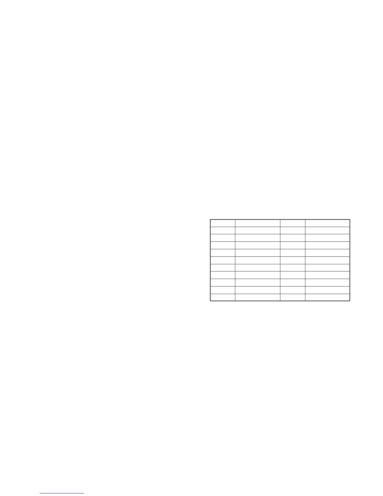
3-1-3. Adjusting Connectors
Some of the adjusting points of the video section are concentrated
at VC-210 board CN2904. Connect the measuring instruments via
the CPC-6 jig (J-6082-370-A) and the CPC-6 terminal board jig (J-
6082-371-A). The following table lists of the pin numbers and signal
names of CN2904.
Pin No.
1
3
5
7
9
11
13
15
17
19
Signal Name
LACN SIG
EVF BL–
EVF VCO
C1 EP
GND
GND
TCK
TDO
SWP
GND
Pin No.
2
4
6
8
10
12
14
16
18
20
Signal Name
EVF BL+
EVF VG
GND
DATA VALID
GND
TMS
TDI
GND
RF IN/LANC JACK IN
RF MON