2-6
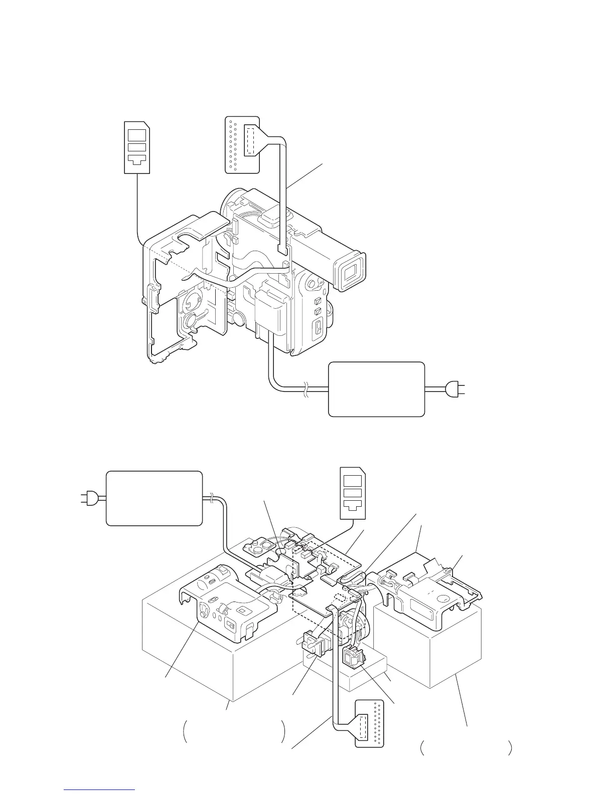
2-8. SERVICE POSITION (Mainly for adjustment)
Firstly: Remove the cabinet (R) referring to section 2-1. Then connect the CPC-6 jig, the adjustment remote commander and the AC adapter
as shown below.
CPC-6 terminal board jig
(J-6082-371-A)
Adjustment remote commander
(RM-95)
AC IN
AC adapter (4.2 Vdc)
(AC-VF10)
CPC-6 flexible jig
(J-6082-370-A)
2-9. SERVICE POSITION (Mainly for voltage measurement)
Firstly: Remove the following followings referring to sections 2-1 to 2-5, and connect them as shown below.
AC adapter (4.2 Vdc)
(AC-VF10)
CPC-6 terminal board jig
(J-6082-371-A)
Adjustment remote commander
(RM-95)
AC IN
DD-111 board
Cabinet (L)
(Control switch block)
(FK-4780)
Base
Supports the cabinet (L),
the VC-210 board and the
DD-111 board using bases.
Lens block
(CD-203 board)
EVF (VF-125 board)
Base
Base
Supports the cabinet (R)
using bases.
MR-40 board
MD block
PD-102 board
Cabinet (R)
(Control switch block)
(ME-4780)
CPC-6 flexible jig
(J-6082-370-A)