2-5
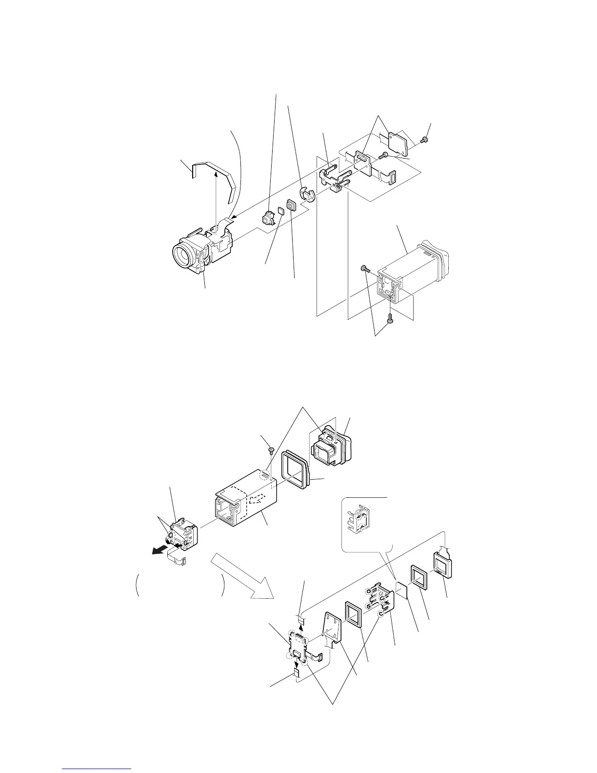
2-6. CD-203 BOARD
1
Three screws (0-No. +P2 tapping M1.7
×
4)
VF lens assembly (Refer to sec. 2-7.)
4
Two screws
(0-No. +P2 B1.7)
5
Two screws
(0-No. +P3 B1.7)
6
CD-203 board
7
CD frame
CCD block assembly
3
Connector
(CD-203 board CN450)
!º
CCD fitting adapter
9
Filter block
8
Sealing rubber
!¡
Lens device (LSV-620A (SOC))
2
Peel lens flexible sheet off.
2-7. VF-125 BOARD
1
Screw (0-No. +P2 M1.7)
5
While pushing the two claws
a
toward inside, remove it in the
direction of arrow
b
.
2
Remove the claws.
3
VF lens assembly
4
VF regulation ring
7
Connector
(VF-125 board CN5502)
VF sleeve assembly
!£
VF-125 board
!¡
Connector (VF-125 board CN5501)
8
LCD
(LCX027AK-J
!™
Remove the four screws.
!∞
VF spacer B
9
VF spacer A
!§
BL bracket
!¢
Light guide plate block, ND902
a
b
6
Be careful of the claw
when removing the VF sheet.
!º
VF sheet
NOTE
When removing the VF,
be careful not to damage
the flexible board.