5-9
1-3. CAMERA SYSTEM ADJUSTMENTS
Before perform the camera system adjustments, check that the
specified value of “Base Band Block Adjustment” of “VIDEO
SYSTEM ADJUSTMENT” are satisfied.
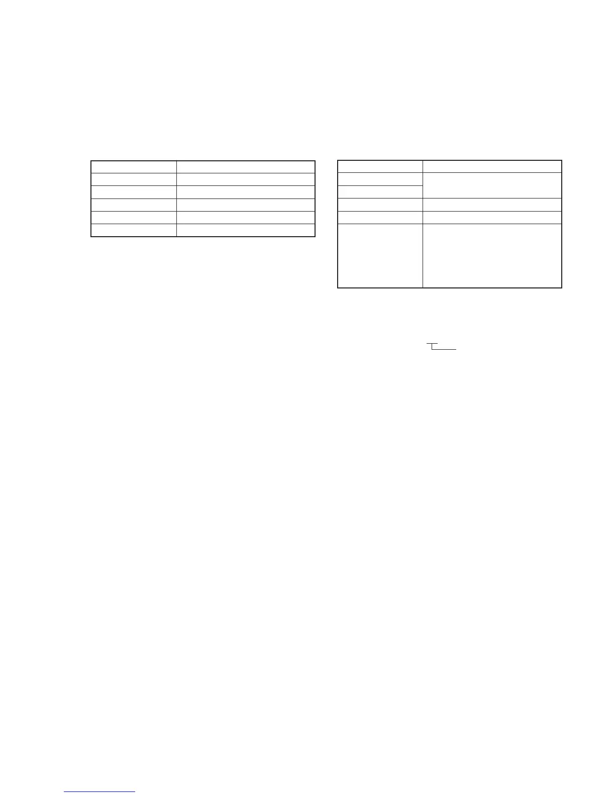
1. 36 MHz Origin Oscillation Adjustment
(VC-210 board)
Set the frequency of the clock for synchronization. If deviated, the
synchronization will be lost and the color will become inconsistent.
Subject Not required
Measurement Point Pin !™ of IC202 (CL200)
Measuring Instrument Frequency counter
Adjustment Page F
Adjustment Address 1C
Specified Value f=18000000 ± 90Hz
Adjusting method:
1) Select page: 0, address: 01, and set data: 01.
2) Select page: F, address: 1C, change the data and set the clock
frequency (f) to the specified value.
3) Press the PAUSE button of the adjustment remote commander.
4) Select page: 0, address: 01, and set data: 00.
2. HALL Adjustment
For detecting the position of the lens iris, adjust the HALL amplifier
gain and offset. If deviated, iris can oscillate, or the indoor-outdoor
white balance can mis-operate.
Subject Not required
Measurement Point DDS display data of LCD or monitor
Measuring Instrument TV (Note 2)
Adjustment Page F
Adjustment Address 1E, 1F, 70
Specified Value When data of page: 6, address: 01 is
01. (Note 1)
Data on display shall be: 88 to 8C.
When data of page: 6, address: 01 is
03. (Note 1)
Data on display shall be: 15 to 19.
Note 1: The PAUSE button of the adjustment remote commander must be
pressed.
Note 2: DDS display data of LCD or TV monitor
CAM 00 0000
CAM 00 00XX
Object data
Adjusting method:
1) Select page: 0, address: 01, and set data: 01.
2) Select page: 6, address: 94, and set data: 8A.
3) Select page: 6, address: 95, and set data: 17.
4) Select page: 6, address: 01, set data: 6D, and press the PAUSE
button of the adjustment remote commander. (The HALL
adjustment is performed and the adjustment data is stored in
page: F, address: 1E, 1F and 70.)
5) Select page: 6, address: 02, and check that the data is “01”.
6) Select page: 6, address: 94, and set data: 00.
7) Select page: 6, address: 95, and set data: 00.
8) Select page: 6, address: 01, set data: 00, and press the PAUSE
button of the adjustment remote commander.
9) Select page: 0, address: 01, and set data: 00.
Checking method:
1) Select page: 0, address: 01, and set data: 01.
2) Select page: D, address: 11, set data: 02, and press the PAUSE
button of the adjustment remote commander.
3) Select page: 6, address: 04, and set data: 03.
4) Select page: 6, address: 01, and set data: 01, and press the
PAUSE button of the adjustment remote commander.
5) Check the DDS display data (Note 2) lies within the “88” to
“8C” range.
6) Select page: 6, address: 01, set data: 03, and press the PAUSE
button of the adjustment remote commander.
7) Check the DDS display data lies within the “15” to “19” range.
8) Select page: 6, address: 01, set data: 00, and press the PAUSE
button of the adjustment remote commander.
9) Select page: 6, address: 04, and set data: 00.
10) Select page: D, address: 11, set data: 00, and press the PAUSE
button of the adjustment remote commander.
11) Select page: 0, address: 01, and set data: 00.