5-22
2. Black Limit Adjustment (PD-102 board)
Set the dynamic range of the LCD driver to an appropriate level.
If deviated, the LCD image will be blackish or saturated (whitish).
Mode VTR stop
Signal No signal
Measuring Point Pin 4 of CN8201 (PSIG)
Measuring Instrument Oscilloscope
Adjustment Page D
Adjustment Address 82
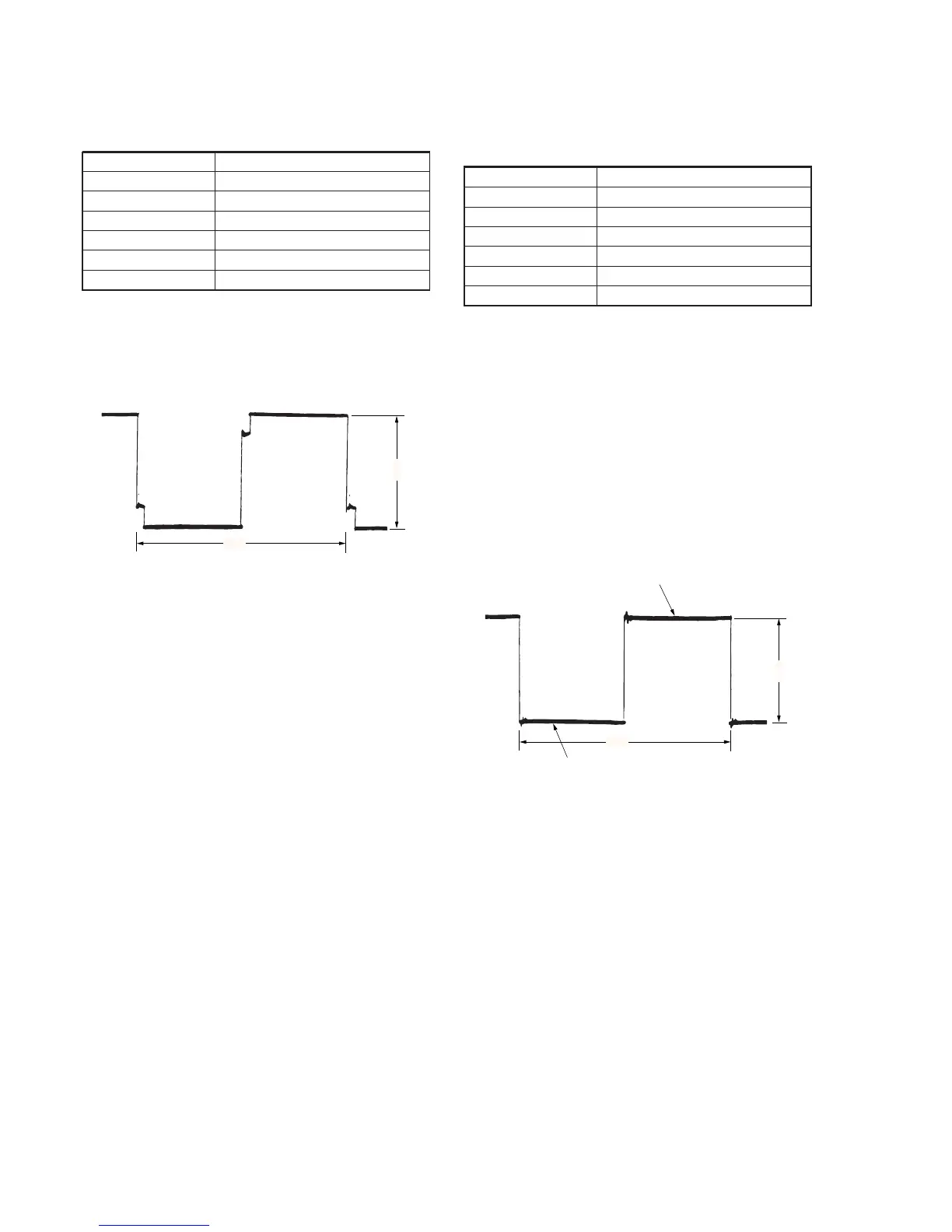
Specified Value A=8.00 ± 0.05V
Adjusting method:
1) Select page: 0, address: 01, and set data: 01.
2) Select page: D, address: 82, change the data until the PSIG
signal amplitude (A) satisfies the specified value.
3) Press the PAUSE button of the adjustment remote commander.
4) Select page: 0, address: 01, and set data: 00.
Fig. 5-1-16
3. Bright Adjustment (PD-102 board)
Set the VIDEO signal level to an appropriate level for driving the
LCD. If deviated, the LCD image will be blackish or saturated
(whitish).
Mode Camera
Subject Arbitrary
Measuring Point Pin 1 of CN8201 (VG)
Measuring Instrument Oscilloscope
Adjustment Page D
Adjustment Address 8A
Specified Value A=7.40 ± 0.05V
Adjusting method:
1) Select page: 0, address: 01, and set data: 01.
2) Select page: 3, address: 0C, set data: 20, and press the PAUSE
button of the adjustment remote commander.
3) Select page: 3, address: 22, set data: 08, and press the PAUSE
button of the adjustment remote commander.
4) Select page: D, address: 8A, change the data and set the voltage
(A) between the inverted waveform's pedestal and non-reversed
waveform's pedestal to the specified value.
5) Press the PAUSE button of the adjustment remote commander.
6) Select page: 3, address: 22, set data: 00, and press the PAUSE
button of the adjustment remote commander.
7) Select page: 3, address: 0C, set data: 00, and press the PAUSE
button of the adjustment remote commander.
8) Select page: 0, address: 01, and set data: 00.
FIg. 5-1-17
A
2H
A
2H
Pedestal
Pedestal