2-2
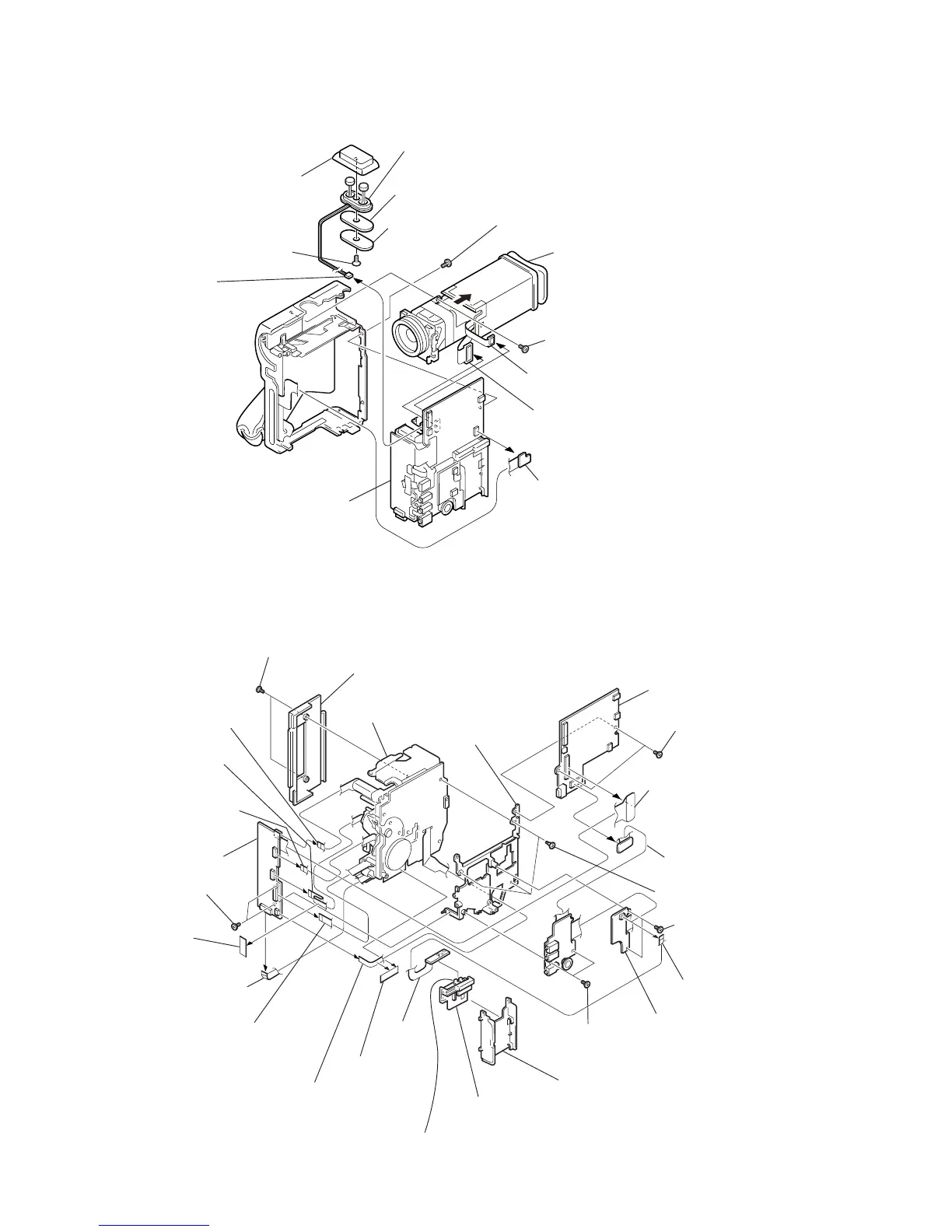
2-2. CABINET (L) ASSEMBLY, EVF, MD BLOCK ASSEMBLY
VC-210
DD-111
Board
MR-40 Board
Board
9
Pan head small screw
(0-No. special M2
×
4)
5
Connector
VC-210 board CN2001
2
Screw (0-No. +P2 M1.7)
3
VF-125 board (VC-210 board CN5000)
4
CD-203 board (VC-210 board CN201
1
Control switch block (FX-4780)
(VC-210 board CN2910)
8
Remove the screw.
(0-No. +P2 M1.7)
7
Move in the direction of
the arrow
a
.
!£
Microphone case assembly
6
MD block assembly
(Refer to sec. 2-3)
!™
Microphone unit
!¡
Microphone GEL sheet
!º
Microphone
retainer plate
a
2-3. VC-210 BOARD, DC-111 BOARD, MF-40 BOARD
V
C
-2
1
0
B
oa
rd
D
D
-1
1
1
M
R
-40 Board
B
o
a
rd
D
D
-1
1
1
@∞
Two screws (Special head, small screw M1.7
×
3.5)
@¡
Two screws
(0-No. +P2 M1.7)
6
Two screws
(0-No. +P2 M1.7)
!ª
Two screws
(0-No. +P2 M1.7)
7
Two screws
(0-No. +P2 M1.7)
5
Battery plate
4
Battery terminal board
!™
Peel adhesive
tape off.
!¡
Peel off the
adhesive tape
(black).
!¢
Flexible board CN2505
(from mode switch)
!£
Flexible board CN2501
(from capstan motor)
!
Flexible board CN1810
(from video head)
!•
FP-586 flexible board CN2504
(from loading motor)
!∞
Flexible board CN2503
(from drum motor)
2
Remove the three solderings from the battery terminal.
@£
Stepped screws (3 pcs