5-18
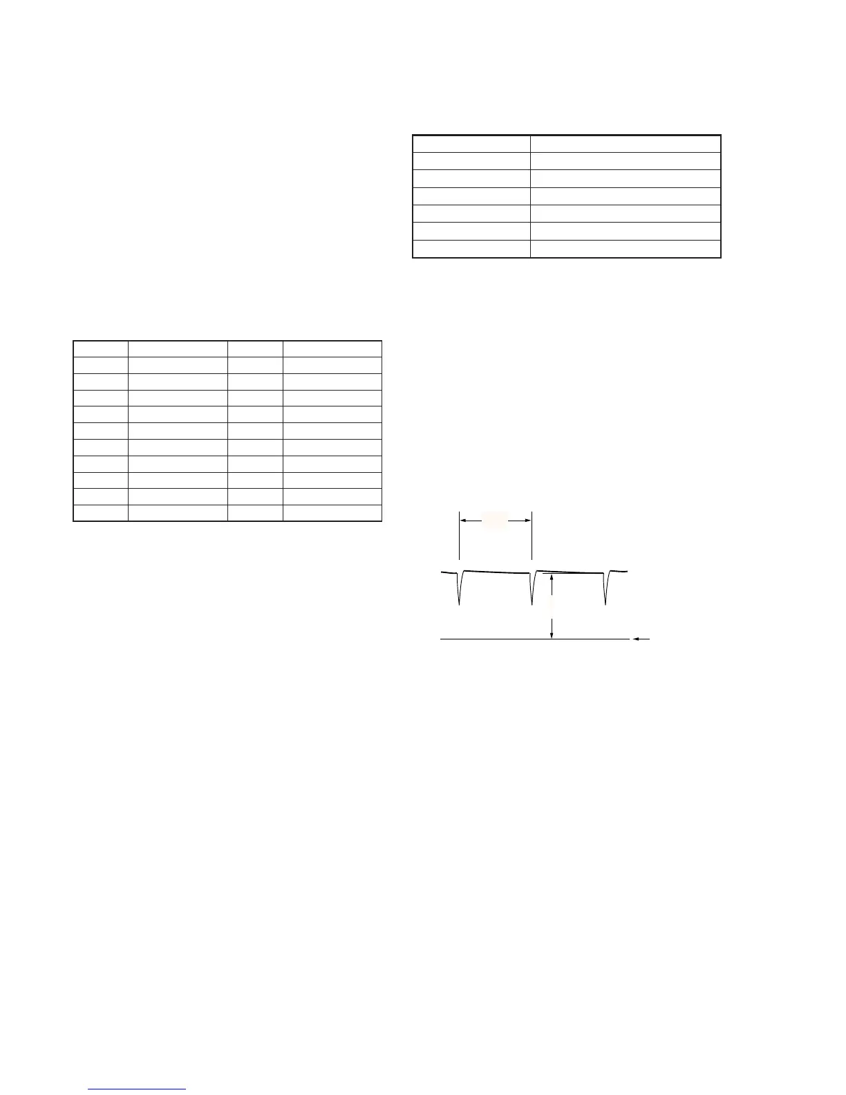
1. VCO Adjustment (VC-210 board)
Set the VCO free-run frequency. If deviated, the LCD display will
be blurred.
Mode VTR stop
Signal No signal
Measurement Point Pin 5 of CN2904 (EVF VCO)
Measuring Instrument Oscilloscope (DC range)
Adjustment Page D
Adjustment Address 75
Specified Value A = 1.75
+ 0.45
V
– 0.35
Adjusting method:
1) Select page: 0, address: 01, and set data: 01.
2) Select page: 3, address: 0C, set data: 20, and press the PAUSE
button of the adjustment remote commander.
3) Select page: 3, address: 22, set data: 02, and press the PAUSE
button of the adjustment remote commander.
4) Check the GND level of the oscilloscope.
5) Select page: D, address: 75, change the data and set the VCO
output voltage (A) to the specified value.
6) Press the PAUSE button of the adjustment remote commander.
7) Select page: 3, address: 22, set data: 00, and press the PAUSE
button of the adjustment remote commander.
8) Select page: 3, address: 0C, set data: 00, and press the PAUSE
button of the adjustment remote commander.
9) Select page: 0, address: 01, and set data: 00.
Fig. 5-1-12
1-4. COLOR ELECTRONIC VIEWFINDER
SYSTEM ADJUSTMENT
Note 1: When replacing the LCD unit, be careful to prevent damages
caused by static electricity.
Note 2: Switch setting
EVF ON/OFF (VC-125 board S5500)
..................................................ON (when the EVF is pulled out)
PANEL OPEN/CLOSE (VC-210 board S2201)
.............................................................CLOSE (Press the switch)
VF BRIGHT (Menu display)...............................................center
[Adjusting connector]
Most of the measuring points for adjusting the LCD are concentrated
in CN2904 of the VC-210 board.
Connect the measuring instruments via the CPC-6 flexible jig (J-
6082-370-A) and CPC-6 terminal board jig (J-6082-371-A). The
following table shows the pin numbers and signal name of CN2904.
Pin No.
1
3
5
7
9
11
13
15
17
19
Signal Name
LACN SIG
EVF BL–
EVF VCO
C1 EP
GND
GND
TCK
TDO
SWP
GND
Pin No.
2
4
6
8
10
12
14
16
18
20
Signal Name
EVF BL+
EVF VG
GND
DATA VALID
GND
TMS
TDI
GND
RF IN/LANC JACK IN
RF MON