5-44
1. Playback Level Check
Mode VTR playback
Signal Alignment tape:
For audio operation check
(XH5-3 (NTSC), XH5-3P (PAL))
Measurement Point AUDIO/VIDEO/HEADPHONES
terminal, R- and L-channels (across
47 kΩ load)
Measuring Instrument Audio level meter and frequency
counter
Specified Value 32 kHz mode: 1 kHz, +3 ± 2 dBs
48 kHz mode: 1 kHz, +3 ± 2 dBs
44.1 kHz mode:
The 7.35kHz signal level during
EMPH ON is –6 ± 2 dB from the
signal level during EMPH OFF
Checking Method:
1) Check that the playback signal level is the specified value.
2. Overall Level Characteristics Check
Mode Camera recording and playback
Signal 1kHz, –66 dBs signal: MIC jack left
and right
Measurement Point AUDIO/VIDEO/HEADPHONES
terminal, R- and L-channels (across
47 kΩ load)
Measuring Instrument Audio level meter
Specified Value –7.5 ± 3.0 dBs
Checking Method:
1) Input the 1kHz, –66 dBs signal into L- and R-ch of the MIC
jack.
2) Record in the camera mode.
3) Playback the recorded section.
4) Check that the L- and R-ch signal levels of AUDIO/VIDEO/
HEADPHONES OUT are the specified value.
3. Overall Distortion Check
Mode Camera recording and playback
Signal 1kHz, –66 dBs signal: MIC jack left
and right
Measurement Point AUDIO/VIDEO/HEADPHONES
terminal, R- and L-channels (across
47 kΩ load)
Measuring Instrument Audio distortion meter
Specified Value Below 0.4 %
(200 Hz to 6 kHz BPF ON)
Checking Method:
1) Input the 1kHz, –66 dBs signal into L- and R-ch of the MIC
jack.
2) Record in the camera mode.
3) Playback the recorded section.
4) Check that L- and R-ch signal levels of AUDIO/VIDEO/
HEADPHONES OUT are the specified value.
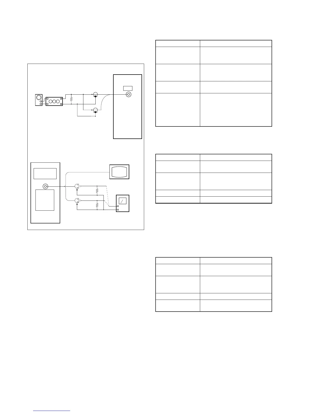
3-6. AUDIO SYSTEM ADJUSTMENTS
[Connection of Audio System Measuring Devices]
Connect the audio system measuring devices as shown in Fig. 5-3-
8.
Fig. 5-3-8
Recording (Camera mode)
Audio
oscillator
Attenuator
600
Ω
Left
Right
Main unit
MIC
600
Ω
: 270
Ω
(1-249-410-11) + 330
Ω
(1-249-411-11)
Main unit
AUDIO/
VIDEO/
HEAD-
PHONES
OUT
Left (White)
Right
47k
Ω
47k
Ω
Video (Yellow)
Monitor TV
Audio level meter
or Distortion meter
47k
Ω
(1-249-437-11)
Playback (VTR mode)
(Red)