5-36
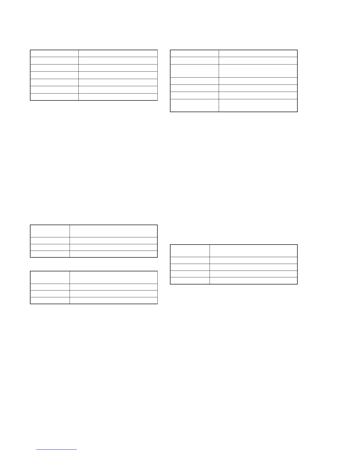
4. Switching Position Adjustment (MR-40 board)
Mode VTR playback
Signal SW/OL reference tape (XH2-3)
Measurement Point Display data of page: 3, address: 03
Measuring Instrument Adjustment remote commander
Adjustment Page C
Adjustment Address 10, 11, 12, 13
Specified Value 00
Adjusting Method:
1) Insert the SW/OL reference tape and enter the VTR STOP
mode.
2) Select page: 0, address: 01, and set data: 01.
3) Select page: 3, address: 21, and check that the data is “02”.
Note: If the data of page: 3, address: 21 is “72”, the tape top is being
played. After playing the tape for 1 to 2 seconds, perform step
4 and higher.
4) Select page: 3, address: 01, set data: 0D, and press the PAUSE
button of the adjustment remote commander.
5) Select page: 3, address: 02, and check the data is changed to
"00".
6) Select page: 3, address: 03, and check that the data is “00”.
Note: If bit 0 of page: 3, address: 03 data is “1”, the even channel is
defective. If bit 1 is “1”, the odd channel is defective. Contents
of the defect is written into page: C, addresses: 10 and 12. See
the following table. (For the bit value, refer to “5-4. SERVICE
MODE”, “4-3. 3. Bit value discrimination”.)
7) Select page: 0, address: 01, and set data: 00.
When the even channel is defective
When the odd channel is defective
5. AGC Center Level Adjustment (MR-40 board)
Mode Camera record and playback
Subject Arbitrary
Measurement Point Pin @º of CN2904 (RF MON) on VC-
210 board (Note 1)
Measuring Instrument Oscilloscope
Adjustment Page C
Adjustment Address 1E
Specified Value The display data of page: 3, address:
03 is “00”
Note 1: Connect a 75 Ω resistor between Pin @º and Pin !ª (GND) of
CN2904.
75 Ω resistor (Parts code: 1-247-804-11)
Adjusting Method:
1) Select page: 0, address: 01, and set data: 01.
2) Select page: 2, address: 30, and set data: 40.
3) Record the camera signal for a minute.
4) Playback the recorded segment.
5) Select page: 3, address: 33, and set data: 08.
6) Confirm that the playback RF signal is stable.
7) Select page: 3, address: 01, set data: 23, and press the PAUSE
button of the adjustment remote commander.
8) Select page: 3, address: 02, and check that the data is changed
to “00”.
9) Select page: 3, address: 03, and check that the data is “00”.
Note: If data of page: 3, address: 03 is other than “00”, adjustment
has errors. (Take an appropriate remedial measures according
to the errors referring to the following table.)
10) Select page: 3, address: 33, and set data: 00.
11) Select page: 2, address: 30, and set data: 00.
12) Select page: 0, address: 01, and set data: 00.
Note 2: If this data is displayed twice successively, the machine is defective.
Data of page: C,
address: 10
EE
E8
E7
Contents of defect
Writing into EEPROM (IC2404) is defective
Adjustment data is out of range
No data is returned from IC1900 (TRX)
Data of page: C,
address: 12
EE
E8
E7
Contents of defect
Writing into EEPROM (IC2404) is defective
Adjustment data is out of range
No data is returned from IC1900 (TRX)
Data of page: 3,
address: 03
20
30
40
50
Remedial measures
Perform re-adjustment. (Note 2)
The machine is defective
Perform re-adjustment. (Note 2)
The machine is defective