5-23
4. Gamma-1 Adjustment (PD-102 board)
Set the VIDEO signal level to an appropriate level for driving the
LCD to the specified value. If deviated, the LCD image will be
blackish or saturated (whitish).
Mode Camera
Subject Arbitrary
Measuring Point Pin 1 of CN8201 (VG)
Measuring Instrument Oscilloscope
Adjustment Page D
Adjustment Address 83
Specified Value A=1.60 ± 0.05V
Note: This (gamma-1) adjustment and the “5. Contrast Adjustment” must
be repeated alternately until both specifications are satisfied
simultaneously (called tracking adjustment).
Adjusting method:
1) Select page: 0, address: 01, and set data: 01.
2) Select page: 3, address: 0C, set data: 20, and press the PAUSE
button of the adjustment remote commander.
3) Select page: 3, address: 22, set data: 02, and press the PAUSE
button of the adjustment remote commander.
4) Select page: 2, address: 0E, and set data: 40.
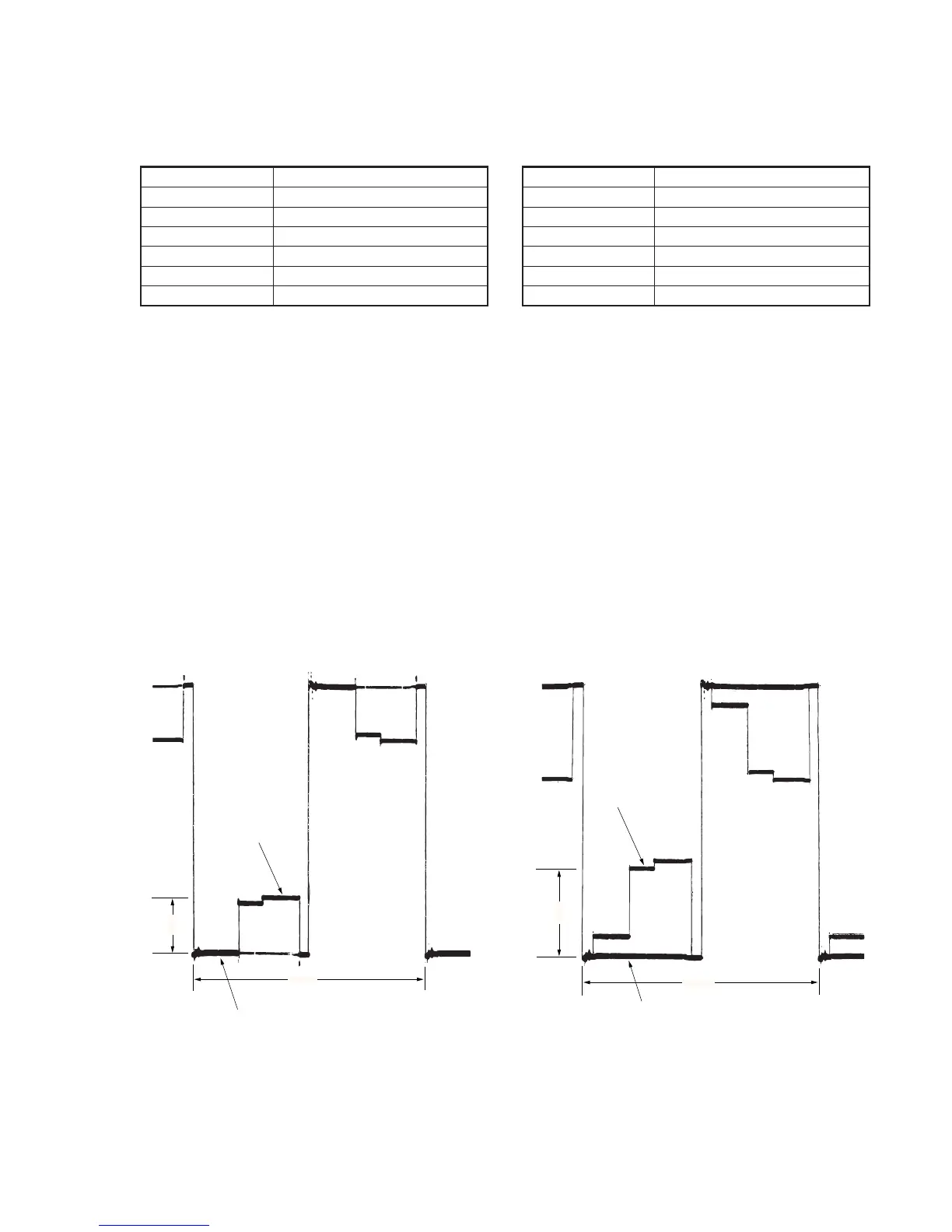
5) Select page: D, address: 83 change the data and set the voltage
(A) between the gamma-1 limiter level and pedestal (0 IRE) to
the specified value.
6) Press the PAUSE button of the adjustment remote commander.
7) Select page: 2, address: 0E, and set data: 00.
8) Select page: 3, address: 22, set data: 00, and press the PAUSE
button of the adjustment remote commander.
9) Select page: 3, address: 0C, set data: 00, and press the PAUSE
button of the adjustment remote commander.
10) Select page: 0, address: 01, set data: 00.
11) Perform “5. Contrast Adjustment”.
Fig. 5-1-18
5. Contrast Adjustment (PD-102 board)
Set the VIDEO signal level to an appropriate level for driving the
LCD to the specified value. If deviated, the screen image will be
blackish or saturated (whitish).
Mode Camera
Subject Arbitrary
Measuring Point Pin 1 of CN8201 (VG)
Measuring Instrument Oscilloscope
Adjusting Page D
Adjusting Address 8C
Specified Value A=2.43 ± 0.05V
Note: This (contrast) adjustment and the "4. Gamma-1 Adjustment" must
be repeated alternately until both specifications are satisfied
simultaneously (called tracking adjustment).
Adjusting method:
1) Select page: 0, address: 01, and set data: 01.
2) Select page: 3, address: 0C, set data: 20, and press the PAUSE
button of the adjustment remote commander.
3) Select page: 3, address: 22, set data: 01, and press the PAUSE
button of the adjustment remote commander.
4) Select page: D, address: 8C, change the data and set the voltage
(A) between 90 IRE and pedestal (0 IRE) to the specified value.
5) Press the PAUSE button of the adjustment remote commander.
6) Select page: 3, address: 22, set data: 00, and press the PAUSE
button of the adjustment remote commander.
7) Select page: 3, address: 0C, set data: 00, and press the PAUSE
button of the adjustment remote commander.
8) Select page: 0, address: 01, and set data: 00.
9) Check that the specified value of the “4. Gamma-1 Adjustment”
is satisfied at this time. If it is found that the specified value is
not satisfied, perform “4. Gamma-1 Adjustment” again, then
perform “5. Contrast Adjustment” once again.
Fig 5-1-19
2H
A
GAMMA 1
limiter
Pedestal
2H
A
90 IRE
Pedestal