7-5
DSR-2000/2000P
P1.4 x 3.5 c
P1.4 x 3.5 a
Positioning hole
Positioning hole
Cleaning
Drum assembly
Positioning pin
Hole
P1.4 x 3.5 b
Positioning pin
Cleaning
Head cleaner assembly
P1.4 x 3.5
P1.4 x 3.5
CN12
7-2. Drum Replacement
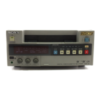
3. Removing the head cleaner assembly
(1) Disconnect the harness connector from the
connector (CN12) on the MS-64 board with
tweezers.
(2) Remove the two screws, and remove the head
cleaner assembly in the direction of the
arrow.
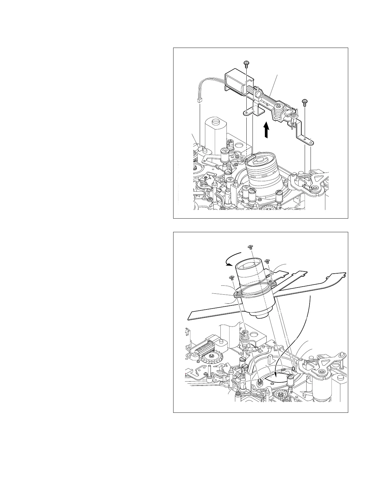
4. Replacing the drum assembly
(1) Remove the three screws, and remove the
drum assembly from the MD chassis.
n
Take care not to contact the drum assembly
to the peripheral tape guides.
(2) Clean the installation surfaces of a new drum
assembly and MD chassis with a cleaning
cloth moistened with cleaning fluid.
(3) Put the five flexible card wires into the hole
on the MD chassis, and align the two posi-
tioning pins on the MD chassis with the holes
of the drum assembly.
(4) While moving the drum assembly in the
direction of the arrow (counterclockwise
direction), tighten the three screws in the
order of a, b, c.
Tightening torque : 0.1 N.m {1 kgf.cm}
 Loading...