7-15
DSR-2000/2000P
Brake base pin
Brake slider assembly
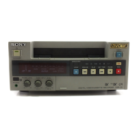
Specification : 0.2 to 0.4 mm
Brake slider assembly
Spring pin
Brake slider assembly
Stop washer
Widen a little in the upward direction
Solenoid iron core
Spring pin
Solenoid
Compression spring
Iron core
Brake slider assembly
Brake base assembly
W2.6
P2.6 x 2.8
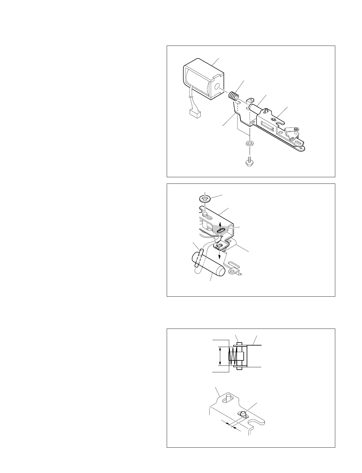
4. Replacing the brake solenoid
Serial No. 100001-100910: UC
400001-401550: CE
(1) Remove the two screws and remove the
solenoid from the brake base assembly.
n
During this operation, the two washers come
off together with the two screws, and further
the compressed coil spring comes off from
the iron core of the solenoid. Be careful not
to lose them.
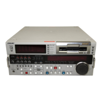
(2) Remove the stop washer shown in the brake
slider assembly figure.
(3) Widen slightly the clearance shown in the
brake slider assembly figure by a finger to
remove the iron core of the solenoid.
n
Applying an excessive force may cause
deformation of the brake slider assembly.
(4) Reattach an iron core pin of a new solenoid to
the brake slider assembly following the same
step (3).
(5) After fitting the compressed coil spring
removed in step (1) on the iron core, insert
the iron core in a new solenoid.
(6) Fix temporally the solenoid positioning as
shown in the figure to the brake base assem-
bly with the two screws and two washers.
(7) Ensure that the compressed coil spring is
placed between the upper and lower plates of
the brake slider assembly (within the double
headed arrow) as shown in the figure.
(8) Adjust the solenoid position to satisfy the
specification of the clearance between the pin
of the solenoid iron core and the slotted hole
in the brake base assembly under the condi-
tion that the iron core is fully pulled in, and
tighten securely the two screws.
Tightening Torque : 0.5 N.m {5 kgf.cm}
(9) Reattach the brake slider assembly to the
brake base assembly with a new stop washer.
7-4. Brake Solenoid Replacement