7-36
DSR-2000/2000P
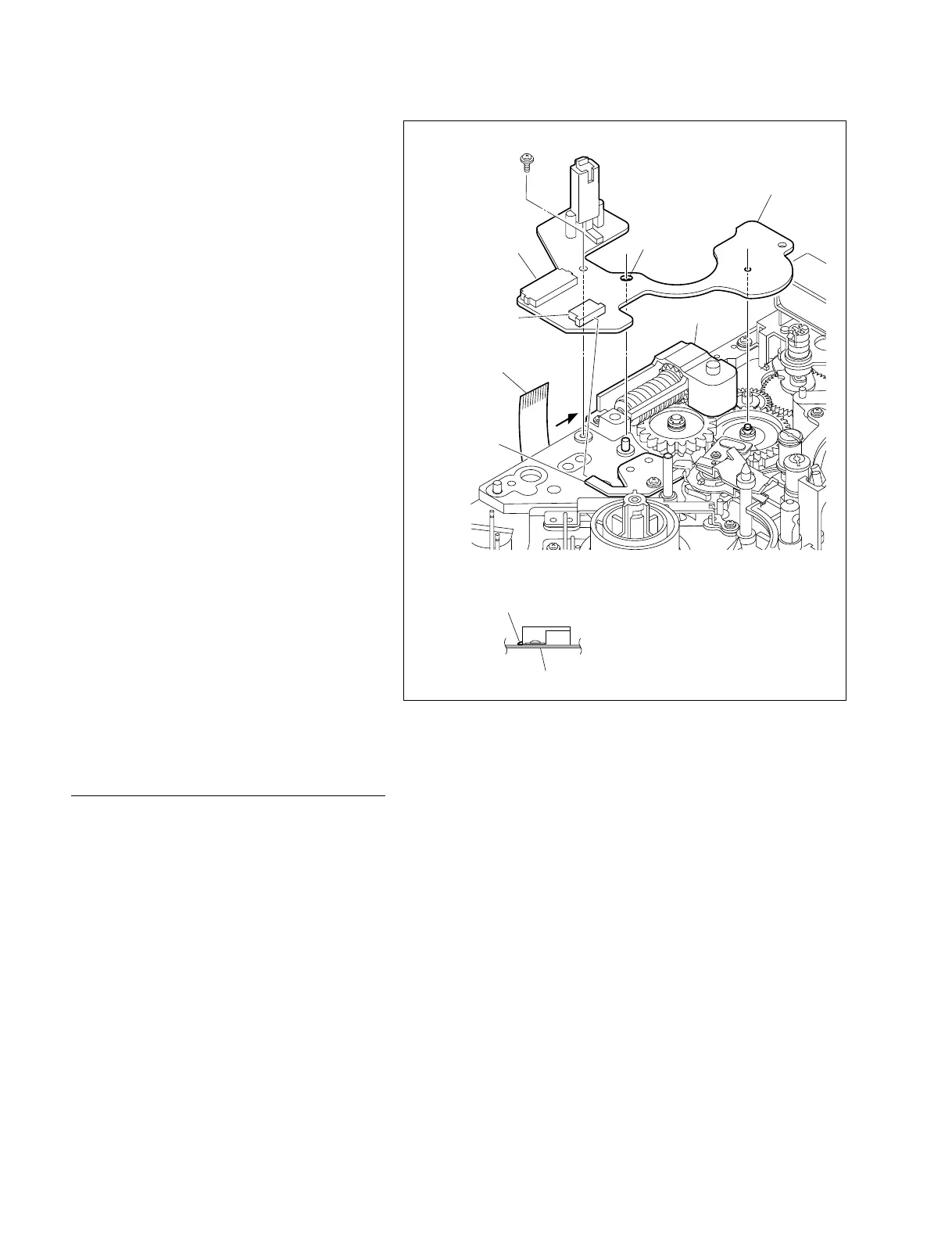
A
Connector (CN3)
SE-521 board
Connector (CN4)
Slotted hole
P1.4 x 3.5
Flexible card wire
Flexible card wire
Worm holder claw
Worm holder
SE-521 board
View from the A point
5. Reattaching the SE-521 board
(1) Fit the hole and slotted hole on the SE-521
board on the two shafts on the MD chassis
respectively and fix it with the screw.
m
. At this operation, be careful not to pinch
the tip of the flexible card wire of the S
tension regulator assembly between the SE-
521 board and the chassis.
. Insert the SE-521 board under the claw of
the worm holder.
(2) Reconnect the flexible card wire to the
connector (CN4) on the SE-521 board.
(3) Reconnect the flexible card wire of the S
tension regulator assembly to the connector
(CN3) on the SE-521 board.
6. Reattaching the loading motor
assembly
Reattach the loading motor assembly.
(Refer to Section 7-17.)
7. Reattaching the TG1 arm assembly
Reattach the TG1 arm assembly.
(Refer to Section 7-13.)
8. Cleaning the tape guide
Wipe the tape guides of the S tension regulator
and the TG1 arm assemblies with a cleaning cloth
moistened with cleaning fluid.
Adjustment after replacement
9. TENSION adjustment
(Refer to Section 5-3-3.)
10. Tape path adjustment
(Refer to Section 8-2.)
7-11. S Tension Regulator Assembly Replacement