7-40
DSR-2000/2000P
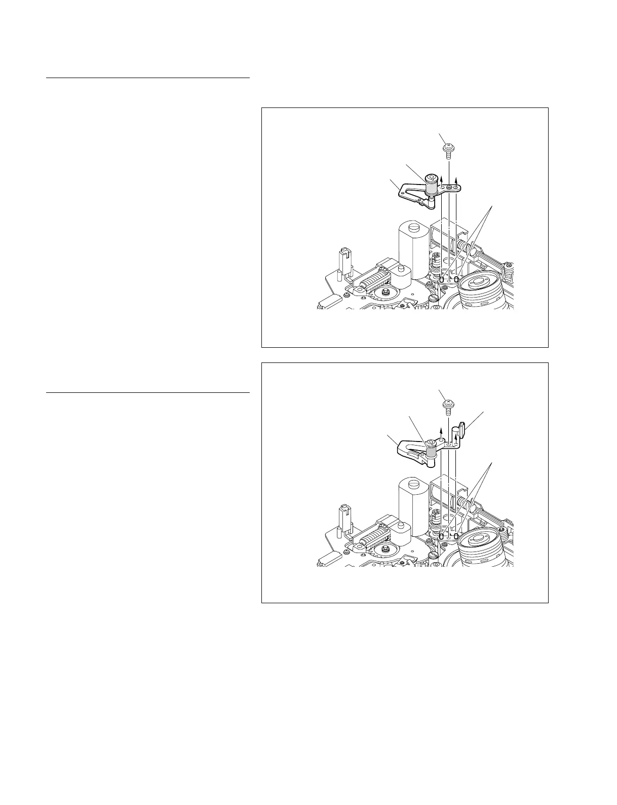
P1.4 x 3.5
TG1 arm assembly
(Part No. A-8279-399-B)
Pins
Tape guide
Serial No, 100911 - 101390 : UC
401551 - 401850 : CE
Fig. 1
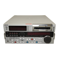
P1.4 x 3.5
TG1 arm assembly
(Part No. A-8279-399-C)
Pins
Tape guide
Tape cleaner
Serial No, 100001 - 100910, 101391 - : UC
400001 - 401550, 401851 - : CE
Fig. 2
Replacement
1. Replacing the TG1 arm assembly
(1) Remove the screw and remove the TG1 arm
assembly from the MD chassis.
(2) Fit two holes in a new TG1 arm assembly on
the two pins on the MD chassis respectively
and fix the assembly with the screw.
Tightening Torque : 0.1 N.m {1 kgf.cm}
2. Cleaning the tape guide
Wipe the tape guide on the TG1 arm assembly
and the tape cleaner with a cleaning cloth moist-
ened with cleaning fluid.
n
The tape cleaner is not used for Serial No.
100911 - 101390 : UC
401551 - 401850 : CE
The set of above serial number, provided ARM
ASSY, TG1 (A-8279-399-C) for repair parts to
stabilize the tape path.
(Refer to Fig. 1 and Fig. 2)
Adjustment after replacement
3. TENSION adjustment
(Refer to Section 5-3-3.)
4. Checking the tape path adjustment
(Refer to Section 8-4.)
7-13. TG1 Arm Assembly Replacement