43
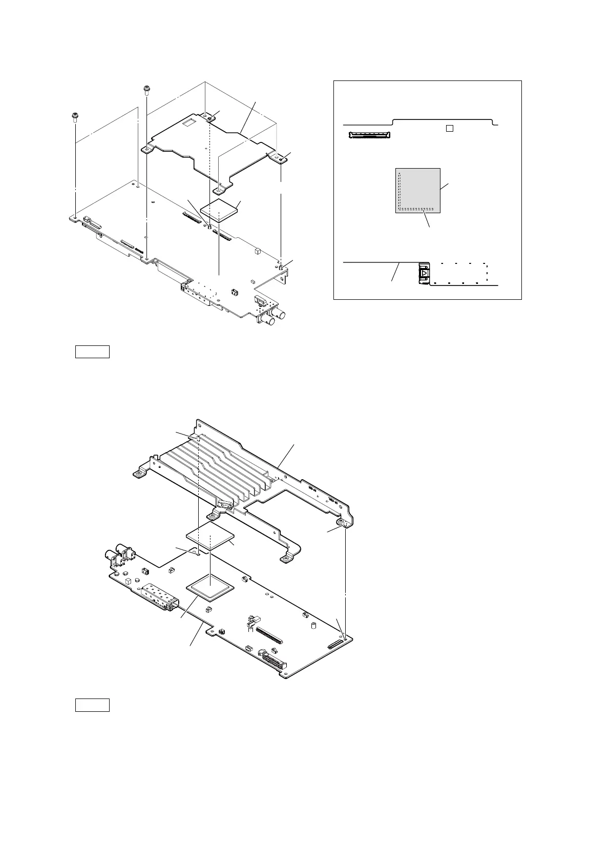
9. Remove the six screws, and then remove the VIF heat sink (B) and the radiation sheet (DPRH).
Note
• When attaching the radiation sheet (DPRH), align it with the line printed on the board.
• At the time of the installation, tighten the screws (a) to (f) sequentially in alphabetical order.
10. Remove the VIF heat sink (A) and the radiation sheet (2(25 x 25)).
Note
When attaching the radiation sheet (2(25 x 25)), match it with the external shape of the IC as shown in the figure.
11. Install the removed parts by reversing the steps of removal.
PSW
3 x 8
PSW
3 x 8
(a)
(e)
(b)
(f)
(c)
(d)
Radiation sheet
(DPRH)
Hole
Hole
Radiation sheet
(DPRH)
Attaching position of the radiation sheet (DPRH)
VIF-82 board
Line
VIF heat sink (B)
Projection
Projection
Radiation sheet
(2(25 x 25))
Hole
Hole
Projection
Projection
VIF heat sink (A)
IC
VIF-82 board