66
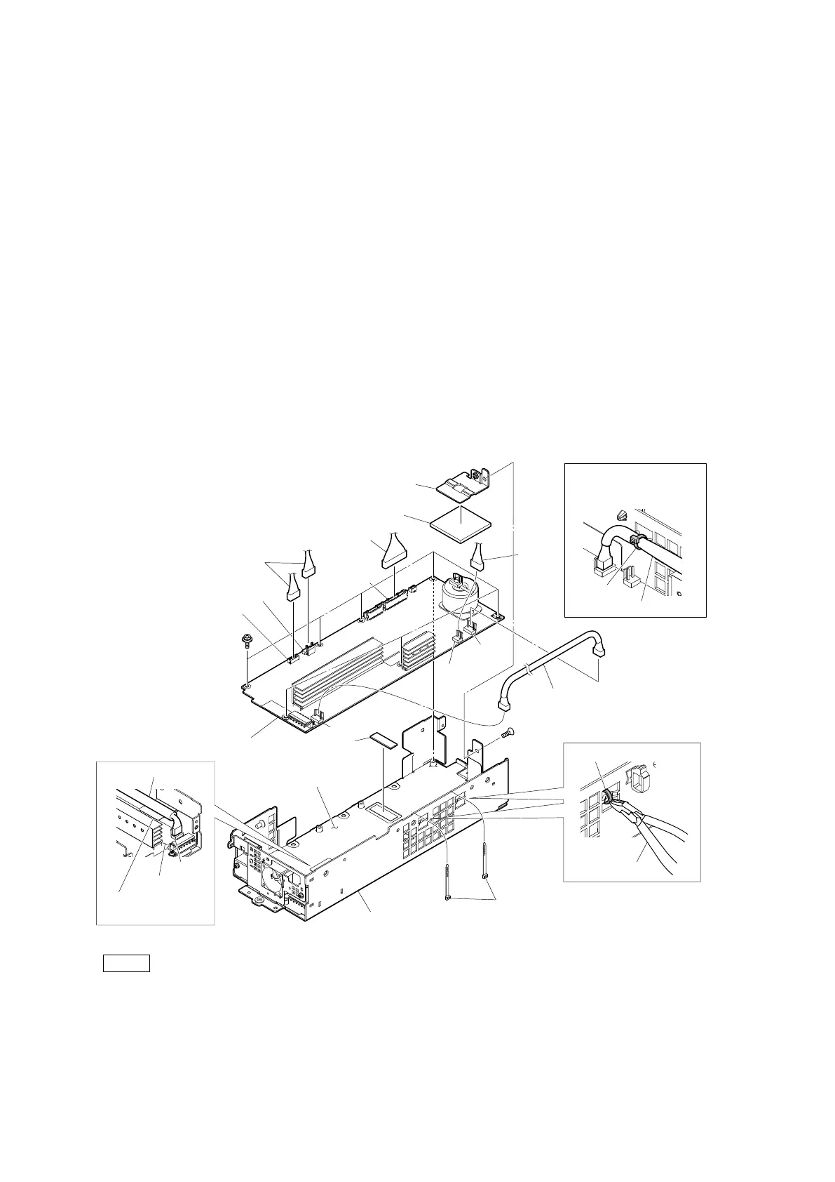
2-13-3. PS-939 Board
Preparation
1. Remove the top cover. (Refer to “2-2. Top Cover”.)
2. Remove the NET-37 board assembly. (Refer to “2-3. NET-37 Board Assembly”.)
3. Remove the front panel assembly. (Refer to “2-4. Front Panel Assembly”.)
4. Remove the VIF-82 board assembly. (Refer to “2-5. VIF-82 Board Assembly”.)
5. Remove the optical multi fiber cable. (Refer to “2-7. Optical Multi Fiber Cables”.)
6. Remove the CN-4132 board. (Refer to “2-8. CN-4132 Board”.)
7. Remove the DC fan subassembly. (Refer to “2-9. DC Fan (60 x 15)”.)
8. Remove the power block. (Refer to “2-13. Power Block”.)
9. Remove the power top assembly. (Refer to “2-13-1. RE-345 Board”.)
Procedure
1. Disconnect the four harnesses from the connectors (CN104, CN105, CN1003 and CN2002) on the PS-939 board.
2. Cut the two binding bands using the nipper.
3. Disconnect the harness from the connectors (CN101 and CN103) on the PS-939 board.
4. Remove the screw (K3 x 6), and then remove the PS coil holder.
5. Remove the radiation sheet (45 x 45) T4.
6. Remove the seven screws (PSW3 x 6), and then remove the PS-939 board.
7. Remove the radiation sheet D.
Note
When installing the PS-939 board, tighten the screws in the following sequence: (a), (b) and others.
8. Install the removed parts by reversing the steps of removal.
PS-939 board
PS-939 board
Radiation
sheet D
Insulating sheet (PS-A)
Bottom case (PS)
CN104
CN101
CN101
(a)
(b)
Harnesses
Harness
PS coil holder
Radiation sheet (45 x 45) T4
Harness
Harness
Cut the remaining part of the
binding band by which the
harness was fixed.
Harness
Binding
band
Binding bands
CN105
CN1003
CN103
CN2002
K3 x 6
PSW
3 x 6
Binding band
Nipper
Put the harness on the
insulating sheet (PS-A).
Harness