48
2-7. Optical Multi Fiber Cables
Note
Do not pull the optical fiber cables strongly or bend them so as not to damage them.
2-7-1. LEMO Connector Assembly
Preparation
1. Remove the top cover. (Refer to “2-2. Top Cover”.)
Procedure
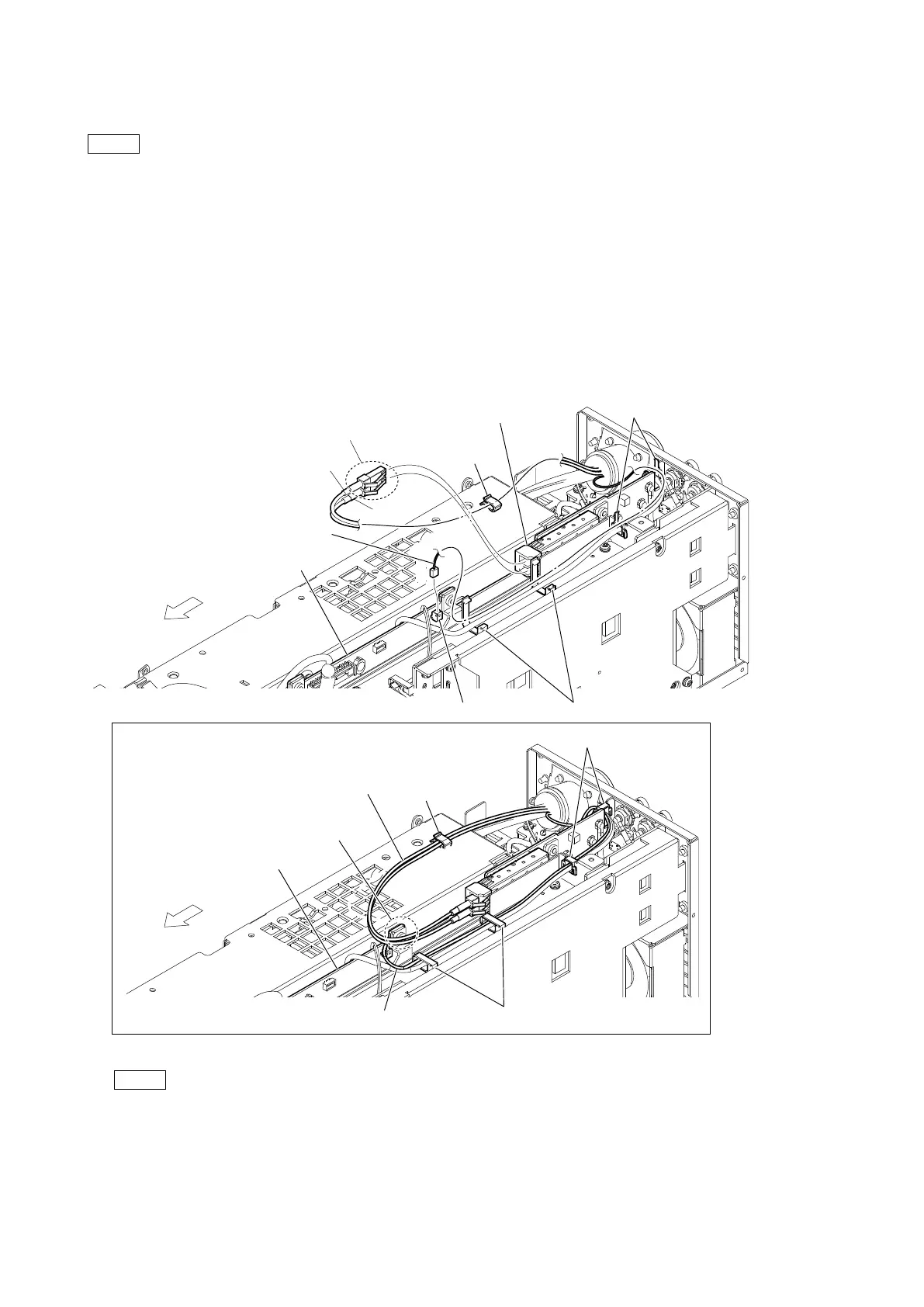
1. Release the harness and the two optical fiber cables from the two locking edge saddles and the two clamps.
2. Disconnect the two optical fiber cables from the optical module (SFP+).
3. Disconnect the harness from the connector (CN404) on the VIF-82 board.
Note
• When connecting the two optical fiber cables, refer to the number indicated on the board.
• At the time of the installation, pass the assembly at the front side of the convex portion of the VIF-82 board as shown below.
• At the time of the installation, arrange the cables as shown in the figure.
[1]
[2]
Optical fiber cables
Optical fiber cables
Arrangement of the cables
VIF-82 board
VIF-82 board
Convex portion
Cable clamps
Cable clamps
CN404
Optical module (SFP+)
Clamp
Clamp
Locking edge saddles
Locking edge saddles
Harness
Harness
* Optical fiber cable [2]: OU
T side
Optical fiber cable [1]: IN side
Front side
Front side