42
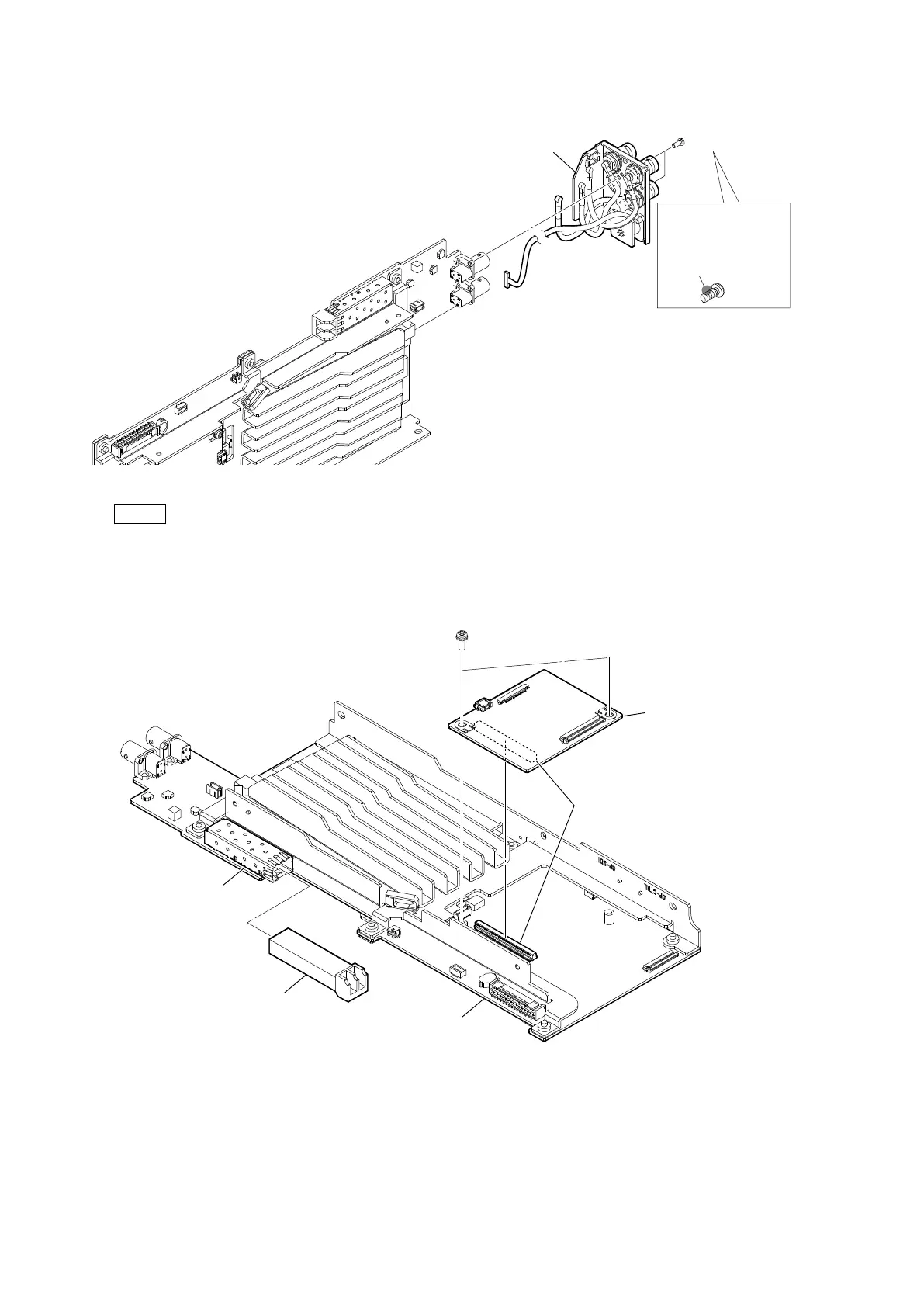
6. Remove the two screws, and then remove the rear connector block.
Note
At the time of the installation, apply locking compound shown in the figure.
7. Remove the two screws, and then remove the AT-195 board.
8. Pull out the optical module (SFP+) from the connector (CN403) on the VIF-82 board.
Locking compound 1401B
(Size of a grain of rice)
Locking compound
application area
P2.6 x 5
Rear connector block
PSW
3 x 8
B to B
connector
AT-195 board
Optical module (SFP+)
VIF-82 board
CN403