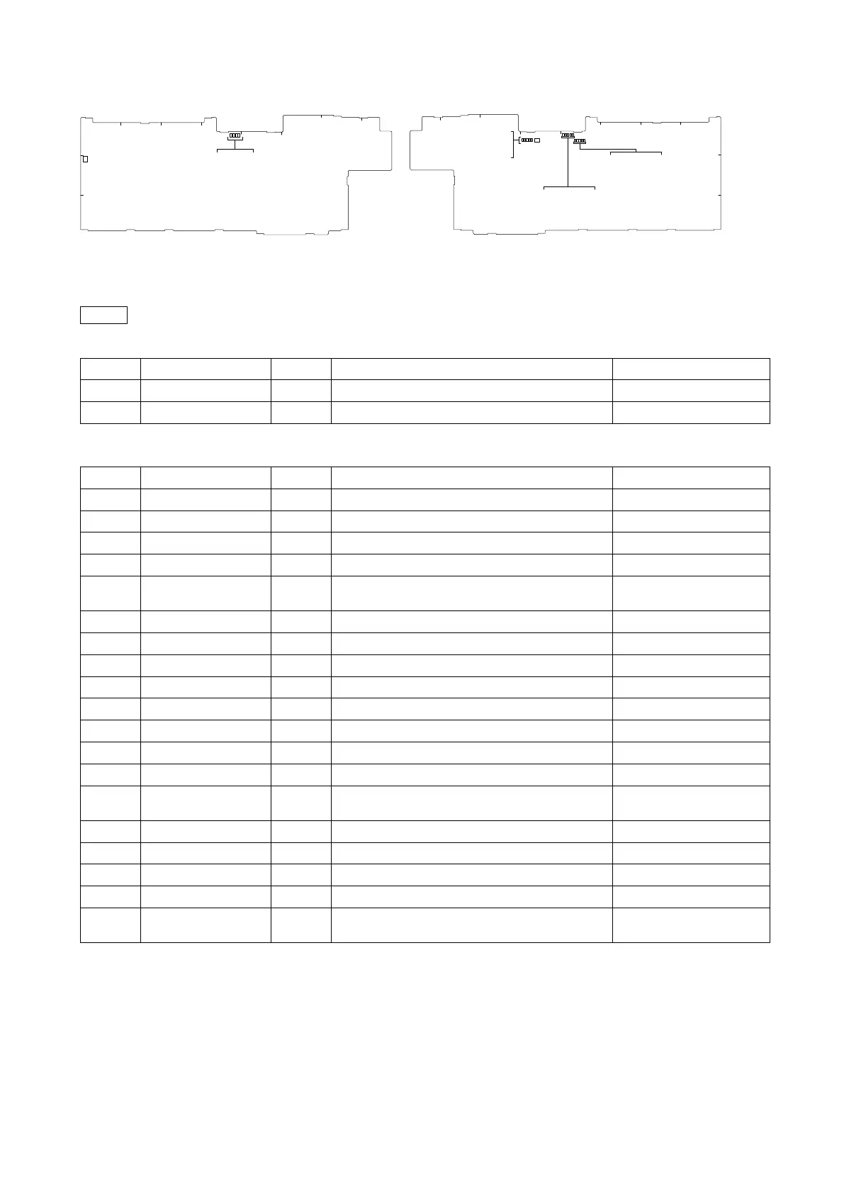
EasyManua.ls Logo

Sony HDCE-TX30 - VIF-82 Board

Sony HDCE-TX30
99 pages
Print Icon
To Next Page IconTo Next Page
To Previous Page IconTo Previous Page
Loading...
7
1-2-2. VIF-82 Board
Switch
Note
Do not change the setting of “Factory use” switch.
Ref. No.
Name
Bit
Description
Factory default setting
S1101
DebugSW
1 to 4
For debugging IC1101
OFF (ALL)
S1401
DebugSW
1 to 4
For debugging IC1401
OFF (ALL)
LED
Ref. No.
Name
Color
Description
Normal State (Power On)
D203
PG3-1
Green
PWRGOOD of IC004 power output
On
D204
PG1
Green
PWRGOOD of power supply IC group 1
On
D205
PG2
Green
PWRGOOD of power supply IC group 2
On
D206
PG3-2
Green
PWRGOOD of IC003 power output
On
D401
TDIS
Red
This LED lights when the optical module output is
activated.
On
D402
TFAULT
Red
This LED lights when an optical module error is detected.
Off
D403
MOD DEF
Red
Unlit when the optical module is connected.
Off
D404
RX_LOS
Red
Unlit when the optical module is receiving light.
Off
D901
EXT
Green
Lit during locking to the external REF signal.
On
D1101
DebugLED
Green
For debugging IC1101
Blinks
D1102
DebugLED
Green
For debugging IC1101
Blinks
D1103
DebugLED
Green
For debugging IC1101
Blinks
D1104
DebugLED
Green
For debugging IC1101
Blinks
D1301
PLD1DONE
Red
This LED goes out after ConfigDone of IC1101 is
performed.
Off
D1401
DebugLED
Green
For debugging IC1401
Blinks
D1402
DebugLED
Green
For debugging IC1401
Blinks
D1403
DebugLED
Green
For debugging IC1401
Blinks
D1404
DebugLED
Green
For debugging IC1401
Blinks
D2001
PLD2DONE
Red
This LED goes out after ConfigDone of IC1700 is
performed.
Off
A
1
2
3
B
C
D
E
F
G
H
VIF-82 Board (Side
A)
S
1101
D204
D205
D203
D206
A
1
2
3
BC
D
E
F
G
H
VIF-82 Board (Side B)
D1104
D1301
D1103
D1102
D
1101
D1404
D2001
D1403
D1402
D1401
D404
D901
D403
D402
D401
S1401

Table of Contents

Related product manuals