63
2-13-1. RE-345 Board
Preparation
1. Remove the top cover. (Refer to “2-2. Top Cover”.)
2. Remove the NET-37 board assembly. (Refer to “2-3. NET-37 Board Assembly”.)
3. Remove the front panel assembly. (Refer to “2-4. Front Panel Assembly”.)
4. Remove the VIF-82 board assembly. (Refer to “2-5. VIF-82 Board Assembly”.)
5. Remove the optical multi fiber cable. (Refer to “2-7. Optical Multi Fiber Cables”.)
6. Remove the CN-4132 board. (Refer to “2-8. CN-4132 Board”.)
7. Remove the DC fan subassembly. (Refer to “2-9. DC Fan (60 x 15)”.)
8. Remove the power block. (Refer to “2-13. Power Block”.)
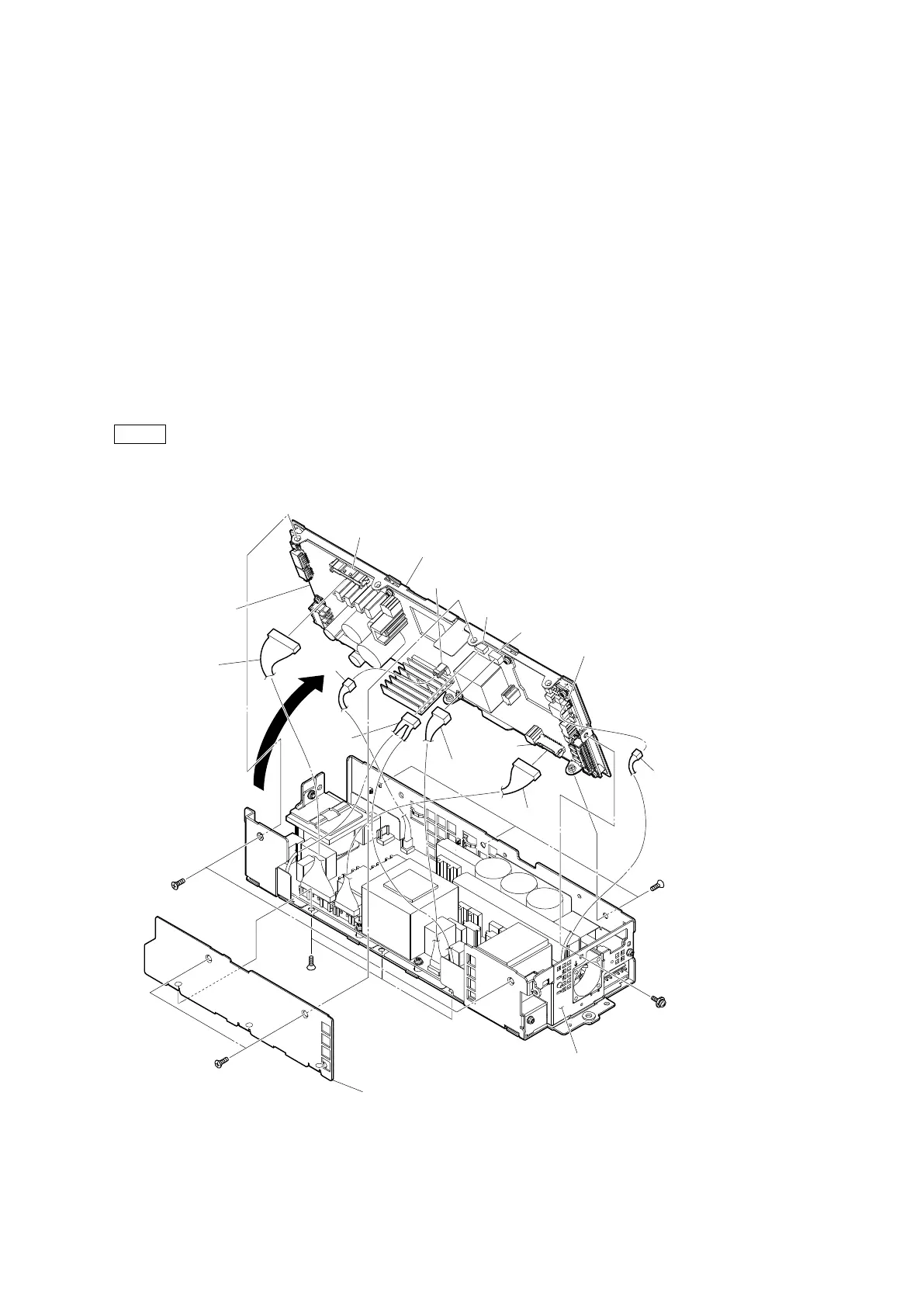
Procedure
1. Remove the five screws (K3 x 6), then remove the side cover (PS).
2. Disconnect the three harnesses from the connectors (CN101, CN102 and CN1003) on the RE-345 board.
3. Remove the five screws (K3 x 6) and the screw (PSW3 x 6), then remove the power top assembly in the direction of the arrow.
4. Disconnect the three harnesses from the connectors (CN1002, CN2002 and CN3001) on the RE-345 board.
Note
• When removing the power top assembly, be careful not to damage the harness connected to the RE-345 board.
• When assembling, attach it with the harness connected to the connector (CN2002) on the RE-345 board brought near the
front panel (PS) side.
PSW
3 x 6
K3 x 6
K3 x 6
K3 x 6
K3 x 6
Harness
Harness
Harness
Harness Harness
Harness
Side cover (PS)
Power top assembly
RE-345 board
CN101
CN102
CN1003
CN1002
CN2002
CN3001
Front panel (PS)