Appendix A: Multiple Chassis Local Connect
Setting Up and Powering Up Multiple Chassis
SmartBits 600x/6000x Installation Guide | 93
To connect multiple synchronized chassis:
1 With power off to all chassis, use a standard Category 5 UTP straight-through cable
and connect the Expansion Out RJ-45 port of the primary controller chassis to the
Expansion In RJ-45 port of a dependent controller chassis. The cable should not
exceed 39 inches or 1 meter in length.
Note: The primary controller chassis uses only the RJ-45 Expansion Out port. It does not
use the RJ-45 Expansion In port. The primary controller chassis is viewed as the first
chassis (Chassis #1) in the series of connected synchronized chassis. See Figure A-4.
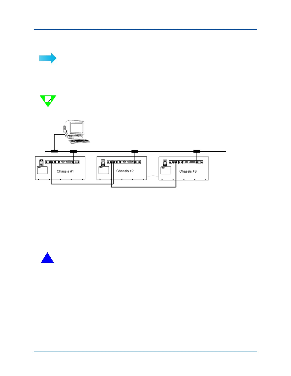
Figure A-4. Example of a Synchronized Multiple Chassis Connection using SmartBits 6000x Chassis
2 Connect the remaining chassis in your system, (Category 5 UTP cables) not to exceed
a total of eight chassis (one primary controller and seven dependent controllers). For
an example, refer to Figure A-3 on page 89.
3 After all the chassis have been connected and the IP addresses have been set, proceed
with “Power Up the Multiple Chassis In Sequential Order” on page 94 for power up
instructions.
!
Caution: To prevent false test results, make sure that the Expansion In and Expansion
Out cables are attached to the proper connectors at each end. Any cables left
disconnected may cause problems.
Primary Controller
192.168.99.1
Dependent Controller
192.168.99.2
Dependent Controller
192.168.99.8
LAN/WAN
Artisan Technology Group - Quality Instrumentation ... Guaranteed | (888) 88-SOURCE | www.artisantg.com