Chapter 2: Installation and Setup
Procedure 4: Connect SmartBits to PC, Power, and LAN
34 | SmartBits 600x/6000x Installation Guide
Procedure 4: Connect SmartBits to PC, Power, and LAN
This procedure explains how to connect the back panel connectors on your SmartBits
chassis. We recommend that you complete Procedures 4 through 10 before you connect to
an application or device under test (Procedures 11/12).
The back panel connectors of the SmartBits 600x/6000x chassis are identical. The chassis
differ only in the location of the power supply connector and the ON/OFF switch.
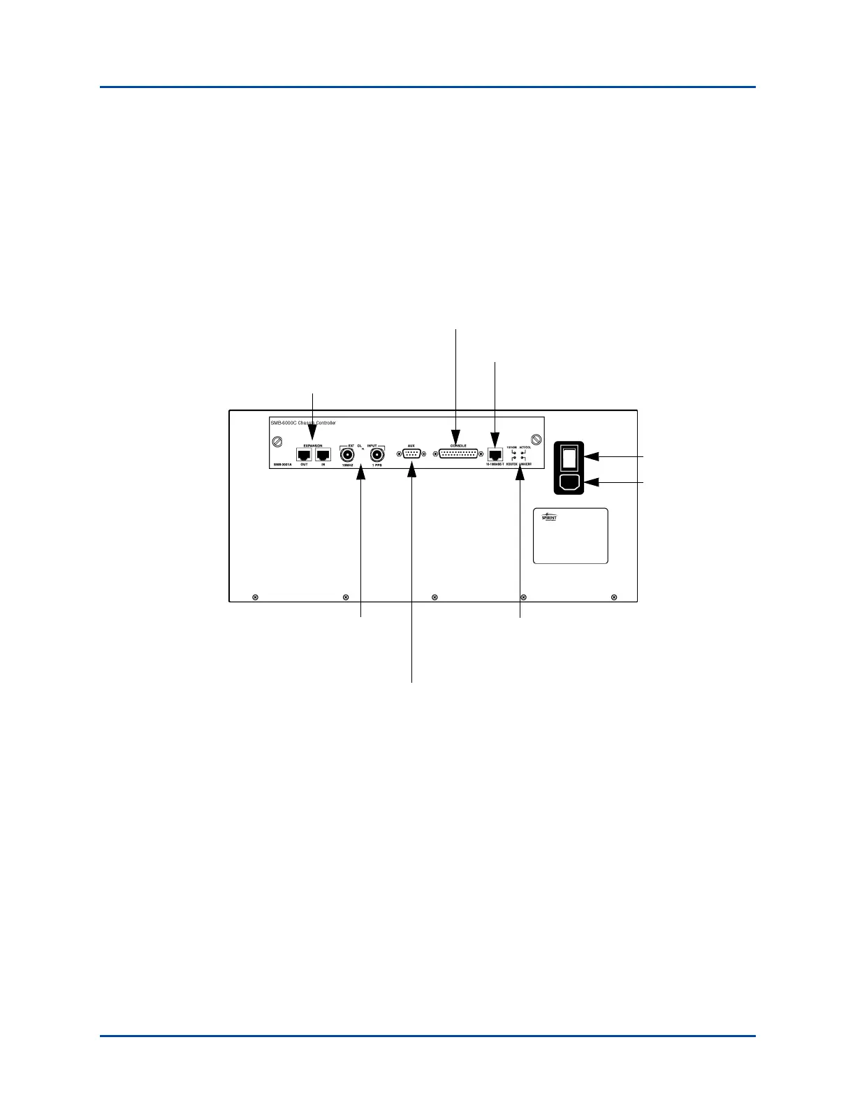
Figure 2-1 shows the back panel on a SmartBits 6000C chassis.
Figure 2-1. SmartBits 6000C Chassis Back Panel Connectors
Serial Console Port
Ethernet
Port
BNC Connectors for
External Clock
Connects to a GPS/
CDMA Receiver
Auxiliary DB9 Connector Connects to a GPS/CDMA Receiver
Master
ON/OFF
Switch
Expansion port (optional) is used to
synchronize timing for up to 8
connected SmartBits chassis
Power Supply
Connector
Back Panel LEDs
for Ethernet Port
Status
Artisan Technology Group - Quality Instrumentation ... Guaranteed | (888) 88-SOURCE | www.artisantg.com