Chapter 2: Installation and Setup
Procedure 4: Connect SmartBits to PC, Power, and LAN
SmartBits 600x/6000x Installation Guide | 35
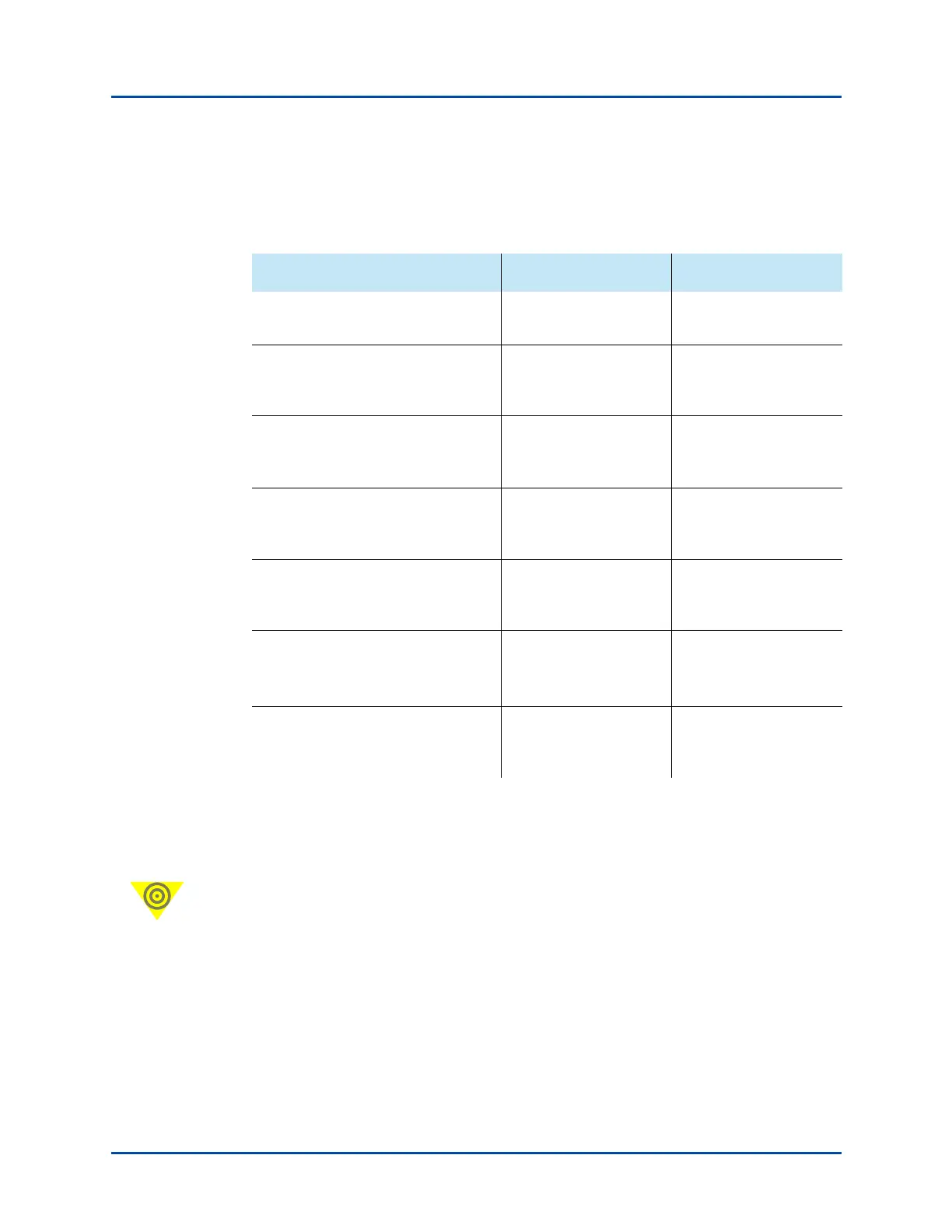
Table 2-1 describes the back-panel connectors, their functions, and the cables to be used
for each connector.
Important: If you are connecting multiple SmartBits chassis for your test environment, it
is critical to power up the chassis in the correct sequence or the test results may be invalid.
Refer to Appendix A, “Multiple Chassis Local Connect” for details. To connect multiple
chassis remotely via GPS/CDMA or a modem, refer to the Using GPS/CDMA with Smart-
Bits Chassis User Guide.
Table 2-1. SmartBits Chassis Connections and Cables
Connect the SmartBits chassis… to … using this cable...
Power supply connector located on
the back panel
Power outlet Power cord
CONSOLE port (DB25) – for IP
address assignment and other
administrative uses
PC Serial port (RS-232) DB9-to-DB9 cable (plus
two DB9-to-DB25
adapters if needed)
10/100BASE-T (RJ-45) port – to
connect a SmartBits chassis to
applications and to the network
Your hub or LAN Blue 10 ft. (3.048 m.)
straight-through
Ethernet LAN cable
10/100BASE-T (RJ-45) port – To
connect a SmartBits chassis directly
to a PC using the Default IP Address
PC White 10 ft. (3.048 m.)
Ethernet crossover cable
EXPANSION OUT or IN RJ-45 port
(optional)
Another SmartBits
chassis and its RJ-45
EXPANSION IN port
Purple 3 ft. (.9144 m.)
straight-through LAN
cable
EXT CLK INPUT port
10 MHz
1
1 PPS
1 These specifications are for interfacing to specific External Time Reference
devices. For further information, see the Using GPS/CDMA with SmartBits Chassis
User Guide (P/N 340-0106-001)
An external timing
device
RG58 coaxial cable
(BNC)
AUX (DB9)
(for GPS/CDMA)
A GPS or CDMA
external time reference
receiver
Not included with the
chassis.
1
Artisan Technology Group - Quality Instrumentation ... Guaranteed | (888) 88-SOURCE | www.artisantg.com