Appendix A: Multiple Chassis Local Connect
Multiple Chassis Connections
SmartBits 600x/6000x Installation Guide | 89
Important: If you fail to follow the power up sequential order, the master controller
(SmartBits 2000) chassis will not recognize the slave unit/s.
7 To power off multiple units in a stack, you must turn off the SmartBits 2000 (master
controller) chassis first and then turn off the slaves.
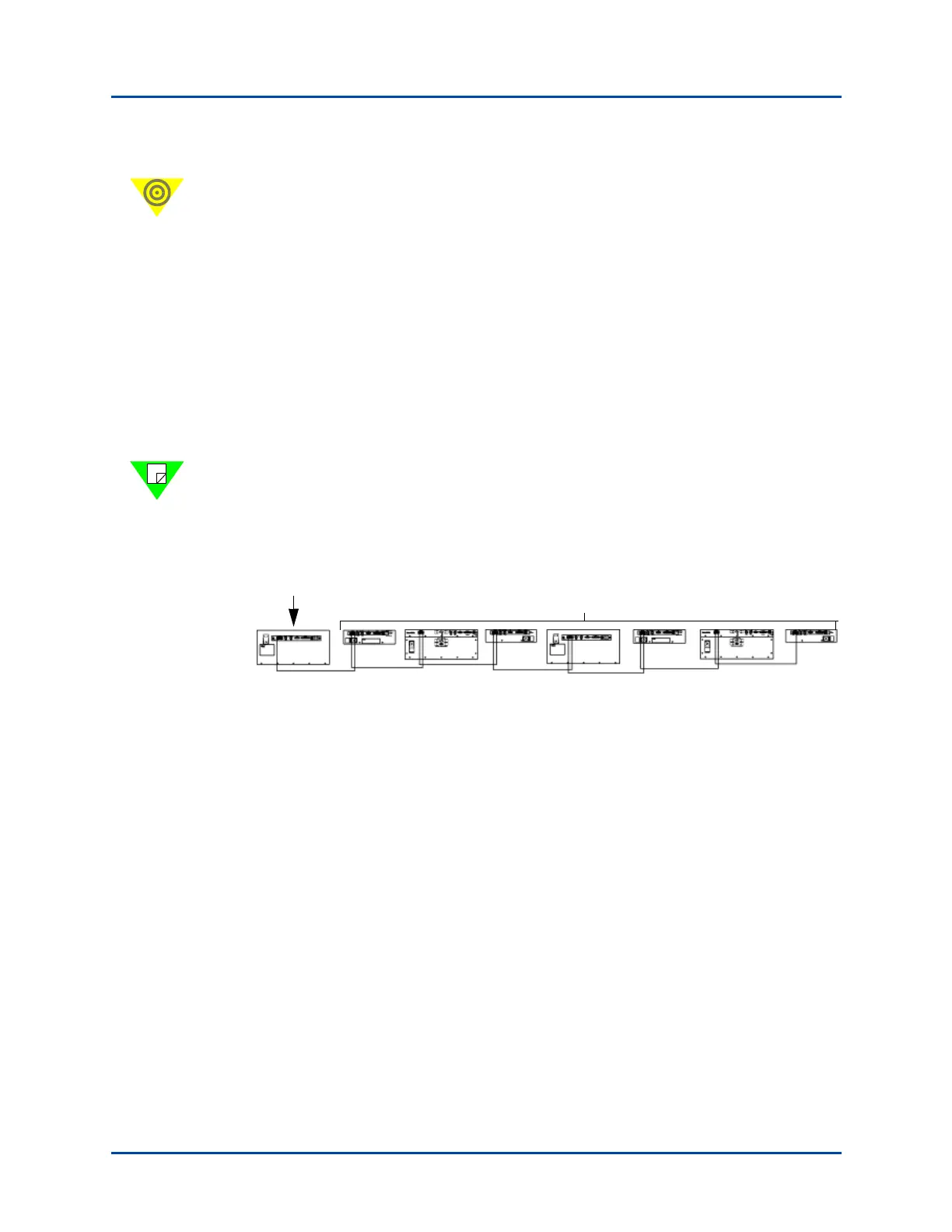
Expansion Connections (all chassis)
An expansion connection involves any combination of SmartBits chassis connected
horizontally, via the RJ-45 expansion connectors using a straight-through Ethernet LAN
cable. You may connect up to eight chassis (one primary controller and seven dependent
controller chassis). This allows for multiple chassis test synchronization with one clock
source (primary controller), which supplies the synchronization in the system. Figure A-3
shows an example of an expansion connection.
Note: Each controller that is connected via expansion needs a separate IP connection to
the application. This cable should have a maximum distance of 3 feet in length. Using
cables longer than 3 feet in length will cause faulty test results. Use the supplied purple
3 foot (.9144 m.) straight-through Ethernet LAN cable for this connection.
Figure A-3. Example of a Multiple Chassis Expansion Connection
If you are using a SmartBits 2000 chassis as the primary controller or one of the
dependent controller chassis, you can also stack and connect up to three additional units
below it via the DB37 ports. In this configuration, the chassis would then become a master
controller chassis as described in “Stacking Connections (SmartBits 2000 chassis only)”
on page 88.
Primary
Controller
Any combination of SmartBits 200/2000 and SmartBits 600x/6000x
Dependent Controller Chassis
3-foot cables only
Artisan Technology Group - Quality Instrumentation ... Guaranteed | (888) 88-SOURCE | www.artisantg.com