Appendix A: Multiple Chassis Local Connect
Multiple Chassis Connections
SmartBits 600x/6000x Installation Guide | 87
Multiple Chassis Connection Terminology
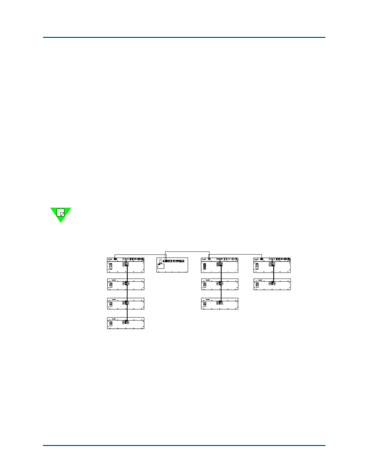
Use Figure A-1 and the descriptions listed below to help you understand multiple chassis
connection terminology.
• Controller – A chassis that can be connected via IP (#4, #5, #8, #10). A controller
can be a SmartBits 200/2000 chassis or a SmartBits 600x/6000x chassis.
• Primary Controller – The controller that supplies the synchronization in an
expansion configuration (#4). A primary controller can be a SmartBits 200/2000
chassis or a SmartBits 600x/6000x chassis.
• Dependent Controller – Any controller that is connected side-by-side, through the
RJ-45 expansion connectors, and relies on the primary controller for synchronization
(#5, #8, #10).
• Master Controller – If a controller is a SmartBits 2000 chassis, it can also be the
master controller (top) chassis in a stacking configuration (#4, #8, #10).
• Slave Unit – In a stacking configuration, a unit (SmartBits 10 or SmartBits 2000) that
relies on the master controller for its source (#1, #2, #3, #6, #7, #9).
Note: Each controller that is connected via expansion needs a separate IP connection to
the application. This cable should have a maximum distance of 3 feet in length. Using
cables longer than 3 feet in length will cause faulty test results. Use the supplied purple
3 foot (.9144 m.) straight-through Ethernet LAN cable for this connection.
Figure A-1. Multiple Chassis Connection Terminology
#1
#2
#3
#4
#5
#6
#7
#8
#9
#10
3 foot cable
3 foot cable
3 foot cable
Artisan Technology Group - Quality Instrumentation ... Guaranteed | (888) 88-SOURCE | www.artisantg.com