Chapter 1: About SmartBits Chassis
Specifications
22 | SmartBits 600x/6000x Installation Guide
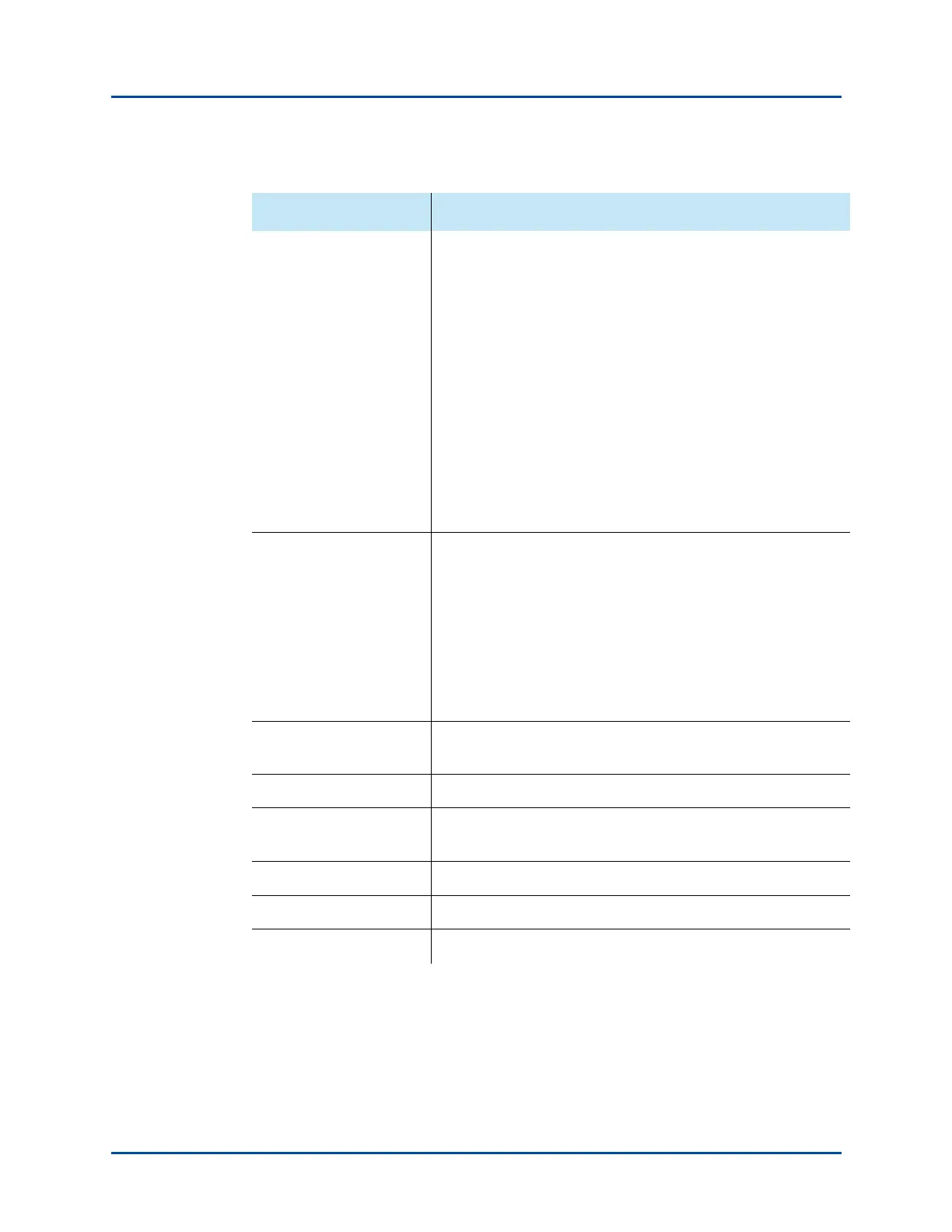
Front Panel LEDs
Back Panel LEDs
SmartBits 600x – POWER, FAN, LINK, STATUS
SmartBits 6000B – POWER, FAN, LINK, STATUS
SmartBits 6000C – POWER and RESET switches;
TEMP, FAN, LINK, STATUS, POWER indicators
SmartBits 600x/6000x – ACT/COL (Activity/Collision), LINK/
ERR (Link/Error), HDX/FDX (Full/Half Duplex), and 10/100M
(10/100 Base Ethernet)
Connectors RS-232 for workstation connection
RJ-45 10/100Base-T connector for Ethernet connection
RJ-45 Expansion In/Out connectors for multiple chassis
connection
Connectors to attach to an optional GPS/CDMA receiver
Layout Requirements Must have unimpeded airflow into the fans at the side of the
chassis
Must meet EMI guidelines (see “Safety Requirements” on page
23)
Must be positioned to meet ESD requirements (see Appendix E,
“ESD Requirements”)
See Appendix A, “Multiple Chassis Local Connect” for
connection and layout information.
GPS/CDMA Option Available Cabling Interface Kits – ACC-1020, ACC-1040,
ACC-1060
NTP Operation Available
Operating temperature 59-104°F (15-40°C). Must have unimpeded airflow into the fans
at the side of the chassis.
Operating Humidity 20 to 80% relative humidity, non-condensing.
Applications Supported See “SmartBits Applications” on page 17
Modules Supported See “Supported Modules” on page 18
Table 1-4. SmartBits 600x/6000x Specifications (continued)
Category Description
Artisan Technology Group - Quality Instrumentation ... Guaranteed | (888) 88-SOURCE | www.artisantg.com