2
2
1
1
-
-
V
V
U
U
M
M
e
e
t
t
e
e
r
r
R
R
e
e
p
p
l
l
a
a
c
c
e
e
m
m
e
e
n
n
t
t
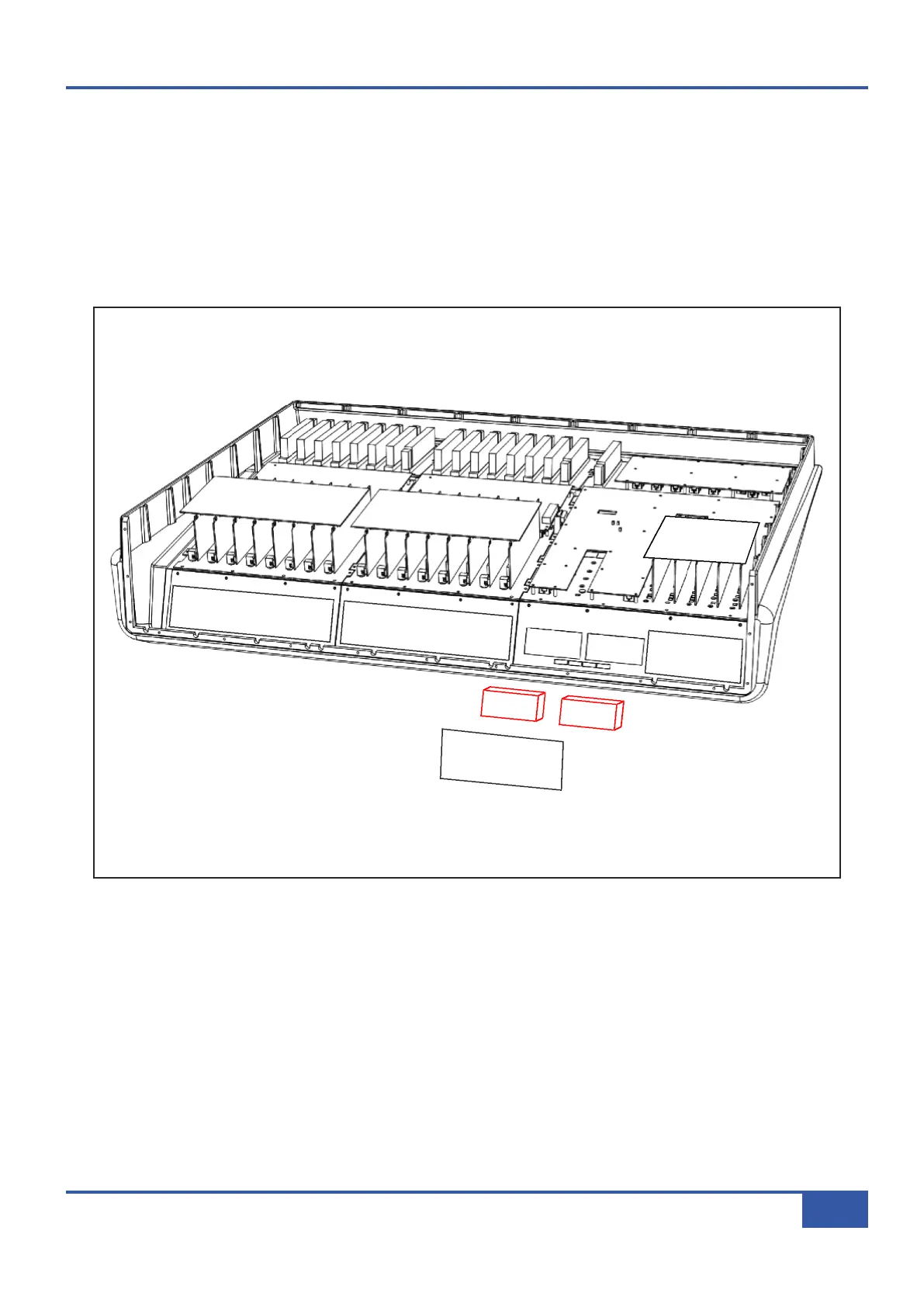
• Follow instruction #2 for removal of the rear connector panel.
• Remove the spade connectors from the rear of the VU meters – making note of which is the positive terminal.
• Remove the three fixing screws and lift the VU PCB clear.
• Using a 6BA nut spinner or spanner remove the two brass fixing nuts from the rear of the VU meter to be replaced.
• Fit the replacement part and reassemble.
•
Follow the calibration procedure on the next page.
Appendix G - Service
139
Matrix Owner’s Manual