Advanced-control timers (TIM1&TIM8) RM0008
325/1128 DocID13902 Rev 15
repetition counter, trigger output features continue to work as normal. Encoder mode and
External clock mode 2 are not compatible and must not be selected together.
In this mode, the counter is modified automatically following the speed and the direction of
the incremental encoder and its content, therefore, always represents the encoder’s
position. The count direction correspond to the rotation direction of the connected sensor.
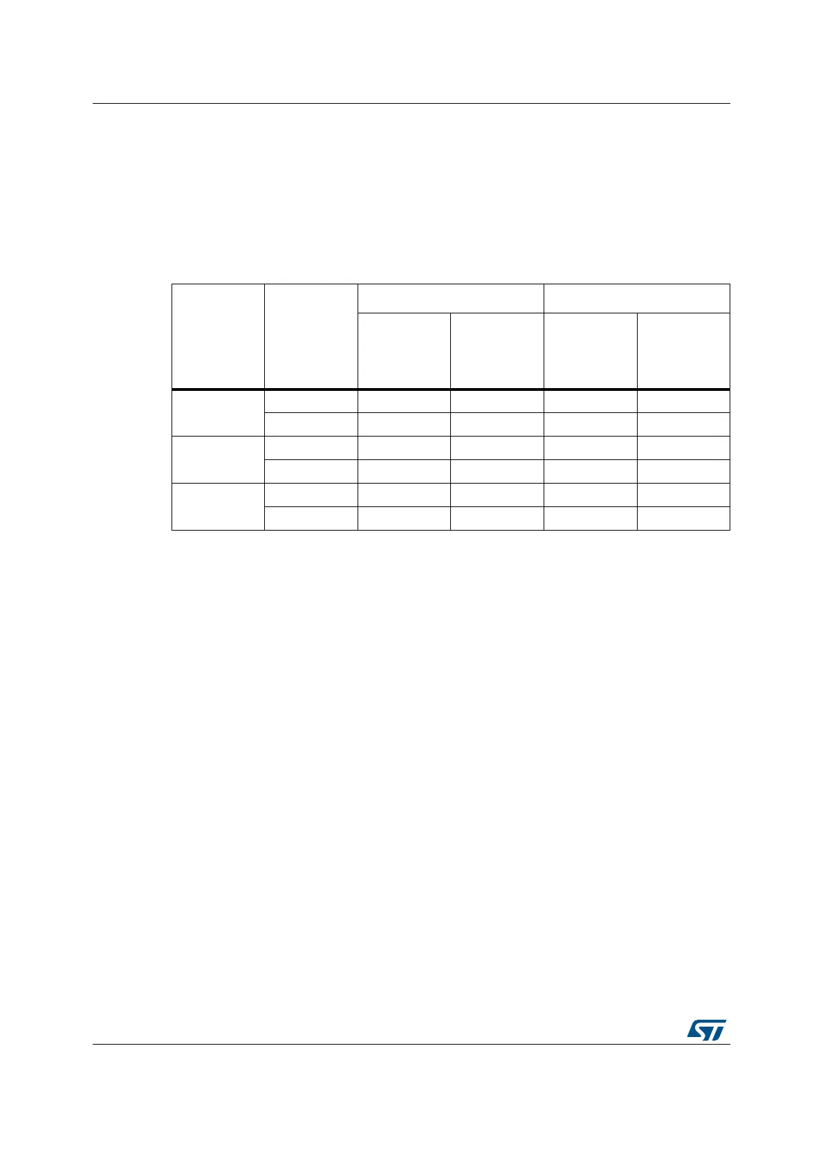
The table summarizes the possible combinations, assuming TI1 and TI2 don’t switch at the
same time.
An external incremental encoder can be connected directly to the MCU without external
interface logic. However, comparators are normally be used to convert the encoder’s
differential outputs to digital signals. This greatly increases noise immunity. The third
encoder output which indicate the mechanical zero position, may be connected to an
external interrupt input and trigger a counter reset.
Figure 93 gives an example of counter operation, showing count signal generation and
direction control. It also shows how input jitter is compensated where both edges are
selected. This might occur if the sensor is positioned near to one of the switching points. For
this example we assume that the configuration is the following:
• CC1S=’01’ (TIMx_CCMR1 register, TI1FP1 mapped on TI1).
• CC2S=’01’ (TIMx_CCMR2 register, TI1FP2 mapped on TI2).
• CC1P=’0’, and IC1F = ‘0000’ (TIMx_CCER register, TI1FP1 non-inverted,
TI1FP1=TI1).
• CC2P=’0’, and IC2F = ‘0000’ (TIMx_CCER register, TI1FP2 non-inverted, TI1FP2=
TI2).
• SMS=’011’ (TIMx_SMCR register, both inputs are active on both rising and falling
edges).
• CEN=’1’ (TIMx_CR1 register, Counter enabled).
Table 81. Counting direction versus encoder signals
Active edge
Level on
opposite
signal (TI1FP1
for TI2,
TI2FP2 for
TI1)
TI1FP1 signal TI2FP2 signal
Rising Falling Rising Falling
Counting on
TI1 only
High Down Up No Count No Count
Low Up Down No Count No Count
Counting on
TI2 only
High No Count No Count Up Down
Low No Count No Count Down Up
Counting on
TI1 and TI2
High Down Up Up Down
Low Up Down Down Up
 Loading...


