Universal serial bus full-speed device interface (USB) RM0008
623/1128 DocID13902 Rev 15
Since the swapped buffer management requires the usage of all 4 buffer description table
locations hosting the address pointer and the length of the allocated memory buffers, the
USB_EPnR registers used to implement double-buffered bulk endpoints are forced to be
used as unidirectional ones. Therefore, only one STAT bit pair must be set at a value
different from ‘00 (Disabled): STAT_RX if the double-buffered bulk endpoint is enabled for
reception, STAT_TX if the double-buffered bulk endpoint is enabled for transmission. In
case it is required to have double-buffered bulk endpoints enabled both for reception and
transmission, two USB_EPnR registers must be used.
To exploit the double-buffering feature and reach the highest possible transfer rate, the
endpoint flow control structure, described in previous chapters, has to be modified, in order
to switch the endpoint status to NAK only when a buffer conflict occurs between the USB
peripheral and application software, instead of doing it at the end of each successful
transaction. The memory buffer which is currently being used by the USB peripheral is
defined by the DTOG bit related to the endpoint direction: DTOG_RX (bit 14 of USB_EPnR
register) for ‘reception’ double-buffered bulk endpoints or DTOG_TX (bit 6 of USB_EPnR
register) for ‘transmission’ double-buffered bulk endpoints. To implement the new flow
control scheme, the USB peripheral should know which packet buffer is currently in use by
the application software, so to be aware of any conflict. Since in the USB_EPnR register,
there are two DTOG bits but only one is used by USB peripheral for data and buffer
sequencing (due to the unidirectional constraint required by double-buffering feature) the
other one can be used by the application software to show which buffer it is currently using.
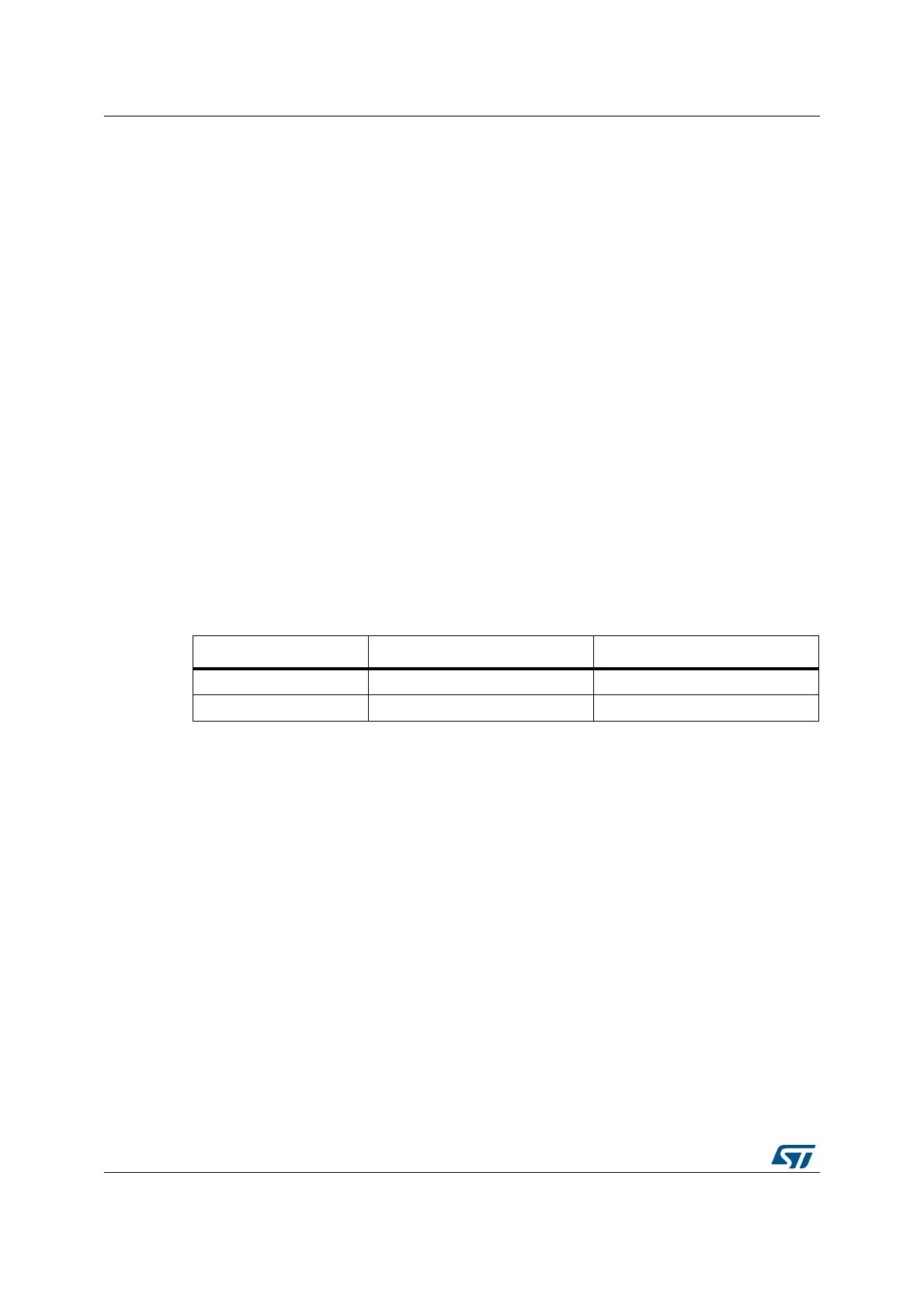
This new buffer flag is called SW_BUF. In the following table the correspondence between
USB_EPnR register bits and DTOG/SW_BUF definition is explained, for the cases of
‘transmission’ and ‘reception’ double-buffered bulk endpoints.
The memory buffer which is currently being used by the USB peripheral is defined by DTOG
buffer flag, while the buffer currently in use by application software is identified by SW_BUF
buffer flag. The relationship between the buffer flag value and the used packet buffer is the
same in both cases, and it is listed in the following table.
Table 169. Double-buffering buffer flag definition
Buffer flag ‘Transmission’ endpoint ‘Reception’ endpoint
DTOG DTOG_TX (USB_EPnRbit 6) DTOG_RX (USB_EPnRbit 14)
SW_BUF USB_EPnR bit 14 USB_EPnR bit 6
 Loading...


