Inter-integrated circuit (I
2
C) interface RM0008
765/1128 DocID13902 Rev 15
26.5 I
2
C debug mode
When the microcontroller enters the debug mode (Cortex
®
-M3 core halted), the SMBUS
timeout either continues to work normally or stops, depending on the
DBG_I2Cx_SMBUS_TIMEOUT configuration bits in the DBG module. For more details,
refer to Section 31.16.2: Debug support for timers, watchdog, bxCAN and I2C on
page 1091.
26.6 I
2
C registers
Refer to Table 2.1 on page 47 for a list of abbreviations used in register descriptions.
The peripheral registers have to be accessed by half-words (16 bits) or words (32 bits).
26.6.1 I
2
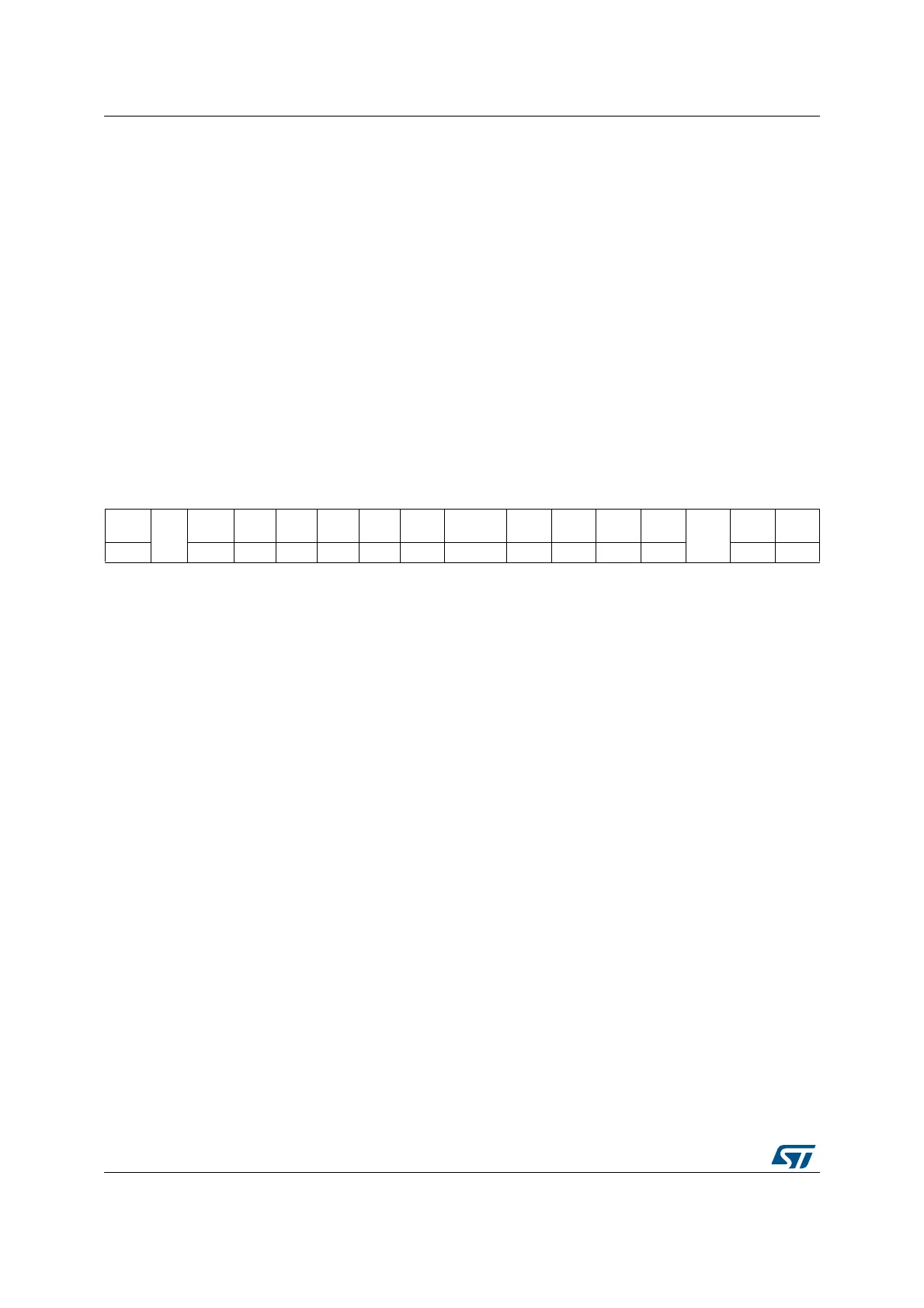
C Control register 1 (I2C_CR1)
Address offset: 0x00
Reset value: 0x0000
15141312111098 7 6543210
SWRST
Res.
ALERT PEC POS ACK STOP START
NO
STRETCH
ENGC ENPEC ENARP
SMB
TYPE
Res.
SMBU
S
PE
rw rw rw rw rw rw rw rw rw rw rw rw rw rw
Bit 15 SWRST: Software reset
When set, the I2C is under reset state. Before resetting this bit, make sure the I2C lines are
released and the bus is free.
0: I
2
C Peripheral not under reset
1: I
2
C Peripheral under reset state
Note: This bit can be used to reinitialize the peripheral after an error or a locked state. As an
example, if the BUSY bit is set and remains locked due to a glitch on the bus, the
SWRST bit can be used to exit from this state.
Bit 14 Reserved, must be kept at reset value
Bit 13 ALERT: SMBus alert
This bit is set and cleared by software, and cleared by hardware when PE=0.
0: Releases SMBA pin high. Alert Response Address Header followed by NACK.
1: Drives SMBA pin low. Alert Response Address Header followed by ACK.
Bit 12 PEC: Packet error checking
This bit is set and cleared by software, and cleared by hardware when PEC is transferred or
by a START or Stop condition or when PE=0.
0: No PEC transfer
1: PEC transfer (in Tx or Rx mode)
Note: PEC calculation is corrupted by an arbitration loss.
 Loading...


