Ethernet (ETH): media access control (MAC) with DMA controller RM0008
969/1128 DocID13902 Rev 15
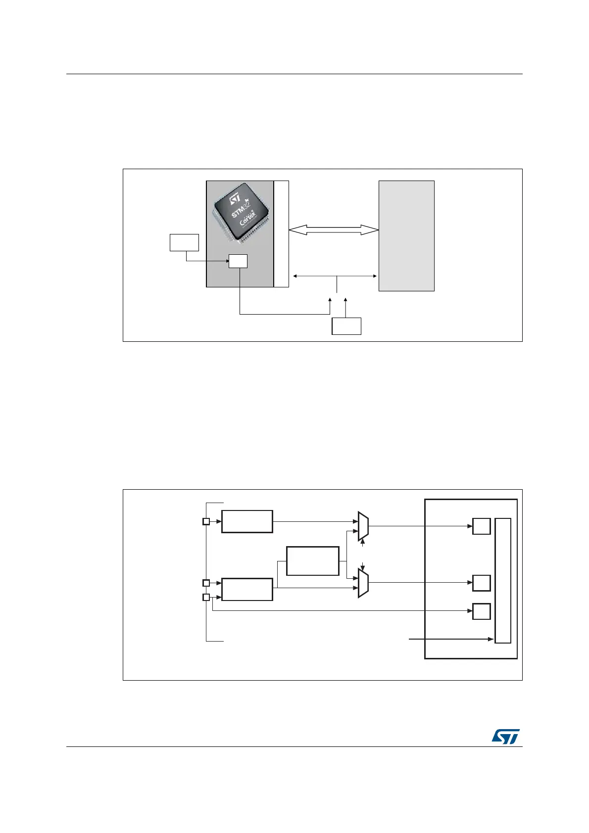
RMII clock sources
As described in the RMII clock sources section, the STM32F10xxxSTM32F107xx could
provide this 50 MHz clock signal on its MCO output pin and you then have to configure this
output value through PLL configuration.
Figure 333. RMII clock sources
29.4.4 MII/RMII selection
The mode, MII or RMII, is selected using the configuration bit 23, MII_RMII_SEL, in the
AFIO_MAPR register. The application has to set the MII/RMII mode while the Ethernet
controller is under reset or before enabling the clocks.
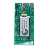
MII/RMII internal clock scheme
The clock scheme required to support both the MII and RMII, as well as 10 and 100 Mbit/s
operations is described in Figure 334.
Figure 334. Clock scheme
1. The MII/RMII selection is controlled through bit 23, MII_RMII_SEL, in the AFIO_MAPR register.
STM32
REF_CLK
50 MHz
50 MHz
MCO
25 MHz
PLL
For 10/100 Mbit/s
External
PHY
ai15625
802.3 MAC
GPIO and AF
controller
GPIO and AF
controller
MII_TX_CLK as AF
(25 MHz or 2.5 MHz)
MII_RX_CLK as AF
(25 MHz or 2.5 MHz)
Sync. divider
/2 for 100 Mb/s
/20 for 10 Mb/s
50 MHz
0
1
0
1
25 MHz or 2.5 MHz
25 MHz or 2.5 MHz
0 MII
1 RMII
(1)
25 MHz
or 2.5 MHz
25 MHz
or 2.5 MHz
MACTXCLK
MACRXCLK
TX
RX
AHB
HCLK
HCLK
MAC
must be greater
than 25 MHz
ai15650
RMII
RMII_REF_CK as AF
(50 MHz)

 Loading...


