STOBER 9 | Connection
05/2019 | ID 442790.01
115
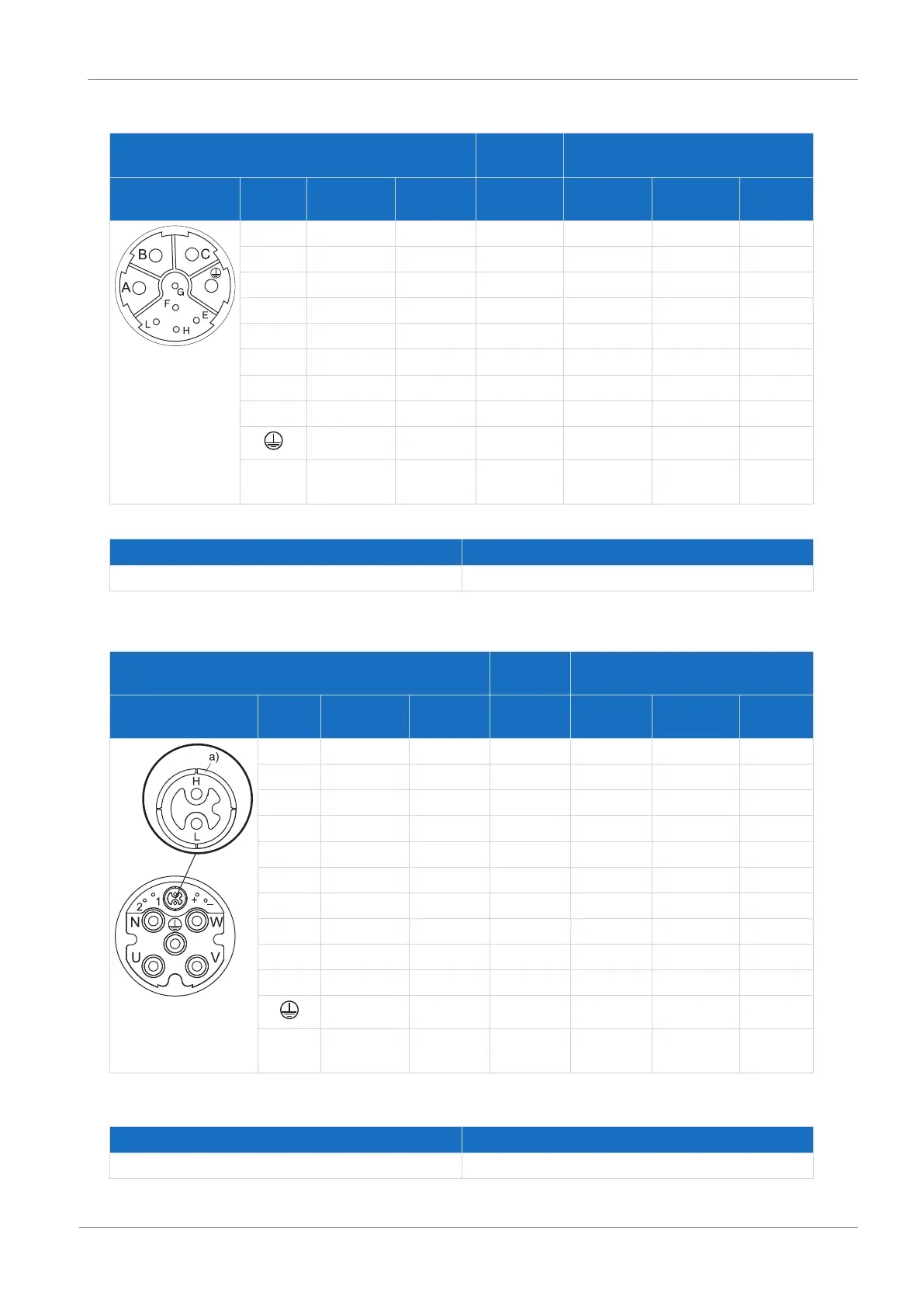
Hybrid cables – con.23 plug connectors
Motor
(1)
Cable
(2)
Drive controller
(3) – (5)
Connection diagram Pin Designation Core color Core No./
Core color
Pin
X20
Pin
X2
Pin
X4
A 1U1 BK L1 1 — —
B 1V1 BU L2 2 — —
C 1W1 RD L3 3 — —
E DSL− GN BU — — 2
F DSL shield — — — — Connector
G 1BD1 RD 5 — 5 —
H DSL+ GY WH — — 4
L 1BD2 BK 6 — 6 —
PE GNYE GNYE 4 —
Housing Shield — — Shield
contact
— —
Tab. 128: con.23 hybrid cable pin assignment
Length x [mm] Diameter y [mm]
78 26
Tab. 129: con.23 connector dimensions
Hybrid cables – con.40 plug connectors
Motor
(1)
Cable
(2)
Drive controller
(3) – (5)
Connection diagram Pin Designation Core color Core No./
core color
Pin
X20
Pin
X2
Pin
X4
U 1U1 BK L1 1 — —
V 1V1 BU L2 2 — —
W 1W1 RD L3 3 — —
N — — — — — —
+ 1BD1 RD 5 — 5 —
− 1BD2 BK 6 — 6 —
F — — — — — —
G — — — — — —
H DSL+ GY WH — — 4
L DSL− GN BU — — 2
PE GNYE GNYE 4 — —
Housing Shield — — Shield
contact
— —
Tab. 130: con.40 hybrid cable pin assignment
a) Coaxial shield to which the DSL shield is connected.
Length x [mm] Diameter y [mm]
99 46
Tab. 131: con.40 connector dimensions

 Loading...


