STOBER 9 | Connection
05/2019 | ID 442790.01
87
9.4.10 X11: 24V supply
The connection of 24V
DC
to X11 is required for the power supply of the control unit.
ATTENTION!
Device damage due to overload!
If the 24 V
DC
power supply is looped to multiple devices over the terminal, the terminal may be damaged by a current that is
too high.
▪ Make sure that the current over the terminal does not exceed the value 15A (UL: 10A).
Electrical data All types
U
1CU
24V
DC
, +20%/−15%
I
1maxCU
0.5A
Tab. 77: Control unit electrical data
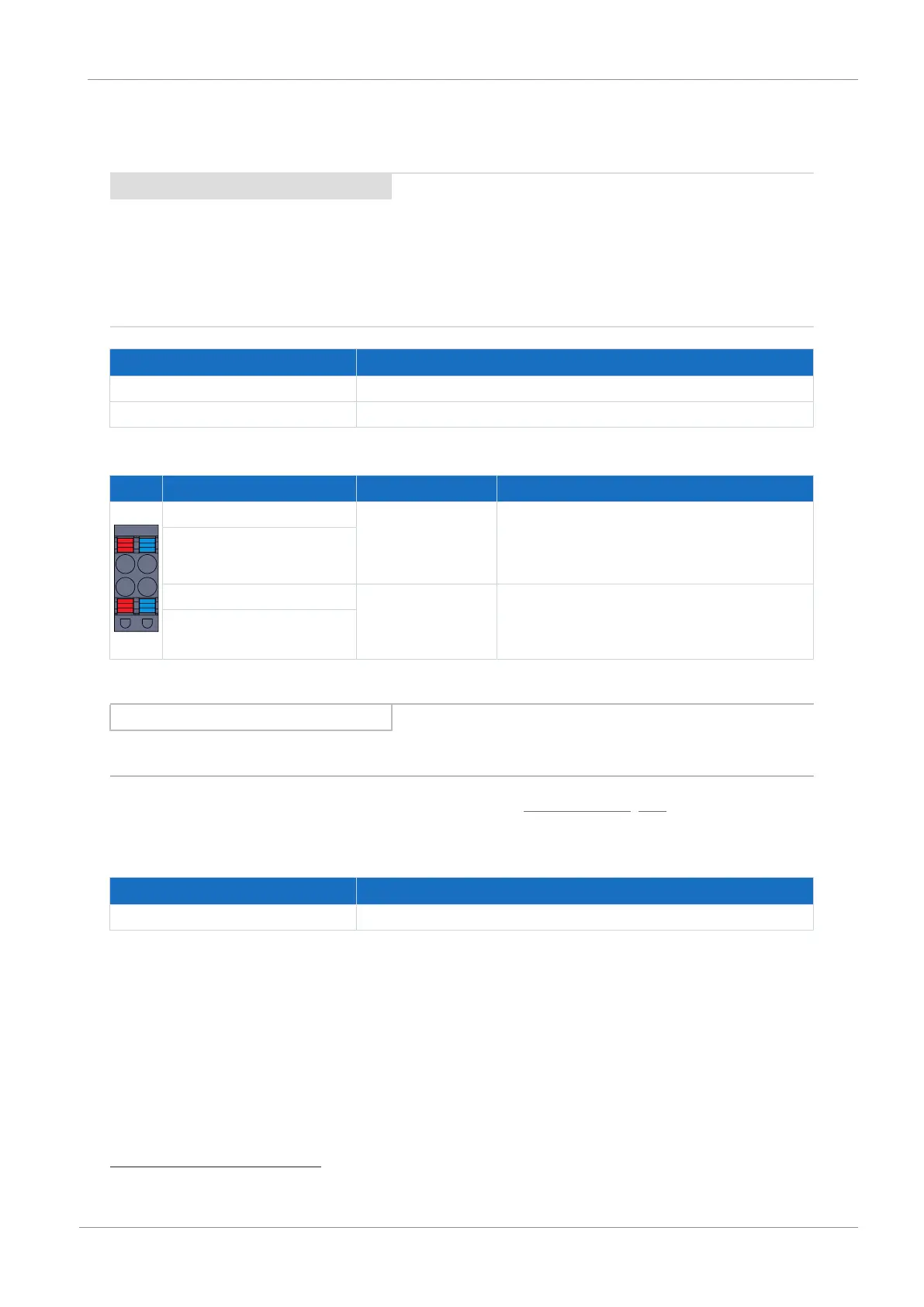
Pin Designation Function
1 | 3
2 | 4
1 + 24V
DC
supply for the control unit; bridged in the
terminal; design in accordance with EN 60204: PELV,
secondary grounded, recommended fuse protection:
max. 15AT
10
2
3 − Reference potential for +24V
DC
, bridged in the
terminal
4
Tab. 78: X11 connection description
Information
The device may not be connected to a DC supply grid. Instead, supply it over a local 24 V
DC
power supply.
For connecting wiring, observe the terminal specifications in the chapter BLDF 5.08 180 SN [}190].
Cable requirements
Feature All sizes
Max. cable length 30m
Tab. 79: Cable length [m]
10
For UL-compliance, use of a 10A fuse (time delay) is required. Be sure that the fuse meets certification requirements for
DC voltage in accordance with UL 248.
 Loading...


