9 | Connection STOBER
86
05/2019 | ID 442790.01
Information
To ensure proper functionality, we recommend using cables from STOBER that are matched to the complete system. If
unsuitable connection cables are used, we reserve the right to reject claims under the warranty.
It is also possible to use cables with the following specification:
Feature Design
Connector wiring Patch or crossover
Quality CAT 5e
Shielding SF/FTP, S/FTP or SF/UTP
Tab. 74: Cable requirements
Device addressing
Information for device addressing can be found in the chapter Device addressing [}195].
9.4.9 X10: 400V supply
Terminal X10 serves to connect the drive controller to the supply grid.
Conductor cross-sections for the power connection
When selecting the conductor cross-section, note the line fuse, the maximum permitted conductor cross-section of
terminal X10, the routing method and the surrounding temperature.
Size 0
Terminal Pin Designation Function
1 | 2 | 3 | 4
1 L1 Power supply
2 L2
3 L3
4 PE Grounding conductor
Tab. 75: X10 connection description, size 0
For connecting wiring, observe the terminal specifications in the chapter GFKC 2,5 -ST-7,62 [}190].
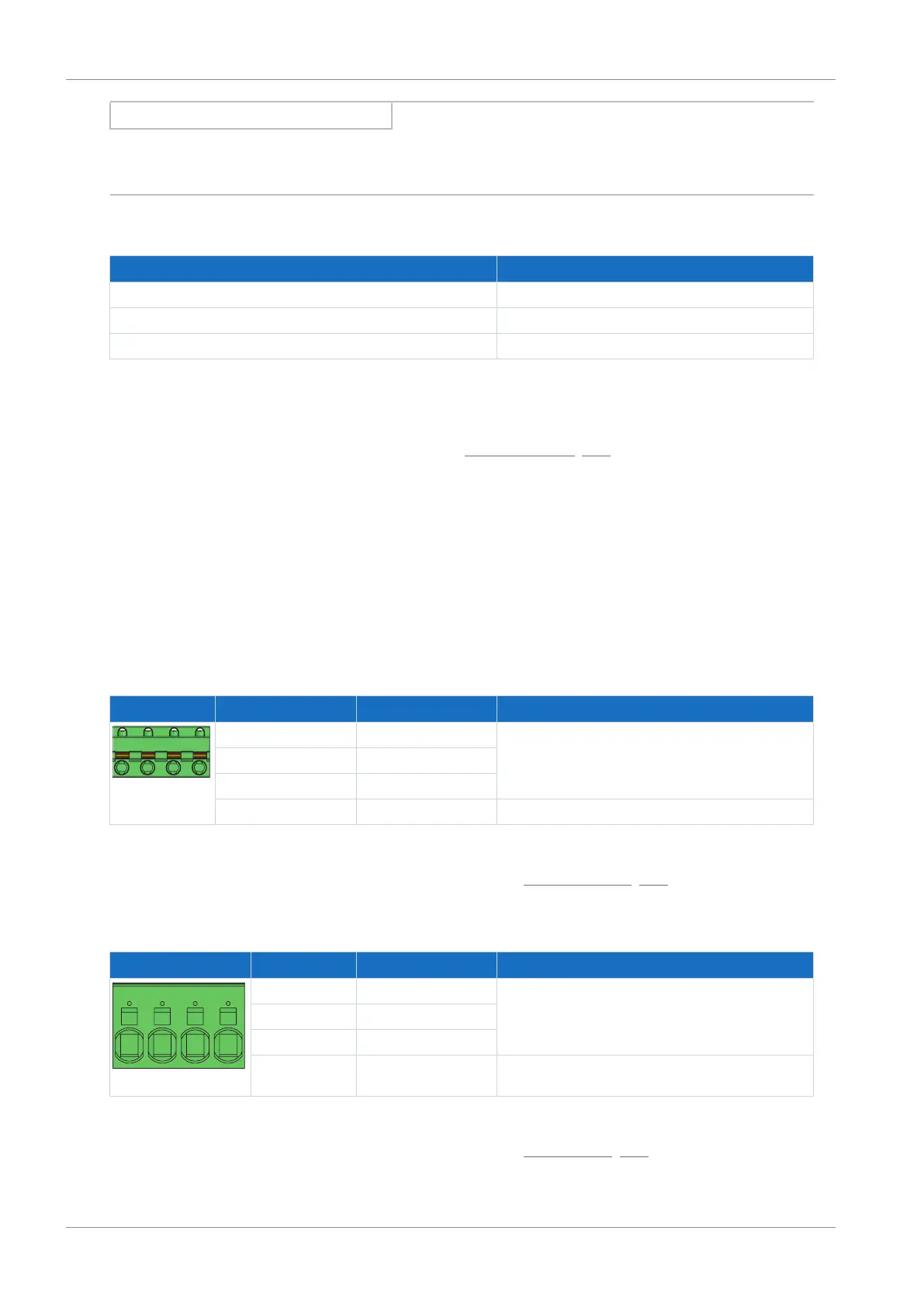
Sizes 1 and 2
Terminal Pin Designation Function
1 | 2 | 3 | 4
1 L1 Power supply
2 L2
3 L3
4 PE Grounding conductor
Tab. 76: X10 connection description, size 1 and 2
For connecting wiring, observe the terminal specifications in the chapter SPC 5 -ST-7,62 [}191].

 Loading...


