STOBER 9 | Connection
05/2019 | ID 442790.01
89
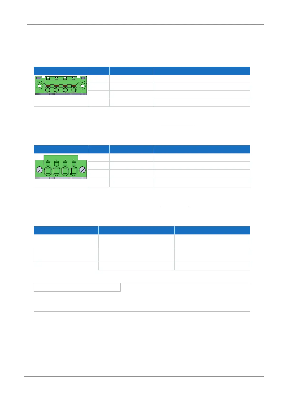
9.4.12 X20A: Motor A
The motor of axis A is connected to X20A.
Size 0
Terminal Pin Designation Function
1 | 2 | 3 | 4
1 U Phase U motor connection
2 V Phase V motor connection
3 W Phase W motor connection
4 PE Grounding conductor
Tab. 82: X20A connection description, size 0
For connecting wiring, observe the terminal specifications in the chapter GFKC 2,5 -ST-7,62 [}190].
Sizes 1 and 2
Terminal Pin Designation Function
1 | 2 | 3 | 4
1 U Phase U motor connection
2 V Phase V motor connection
3 W Phase W motor connection
4 PE Grounding conductor
Tab. 83: X20A connection description, sizes 1 and 2
For connecting wiring, observe the terminal specifications in the chapter SPC 5 -ST-7,62 [}191].
Cable requirements
Motor type Connection Size 0 to 2
Synchronous servo motor,
asynchronous motor
Without output choke 50m, shielded
Synchronous servo motor,
asynchronous motor
With output choke 100m, shielded
Lean motor Standard 50m, shielded
Tab. 84: Maximum cable length of the power cable [m]
Information
To ensure proper functionality, we recommend using cables from STOBER that are matched to the complete system. If
unsuitable connection cables are used, we reserve the right to reject claims under the warranty.
Shielded connection of the power cable
Note the following points for the connection of the power cable:
§ Ground the shield of the power cable on the shield contact on the drive controller intended for this.
§ Keep the exposed conductors as short as possible. All devices and circuits that are sensitive to EMC must be kept at a
distance of at least 0.3m.

 Loading...


