STOBER 9 | Connection
05/2019 | ID 442790.01
93
9.4.17 X103: BE6 – BE9
The binary inputs 6 to 9 are available on terminal X103.
X103 for binary signals
For the evaluation of binary signals at X103, observe the technical data of the drive controller; see the chapter Binary inputs
[}33].
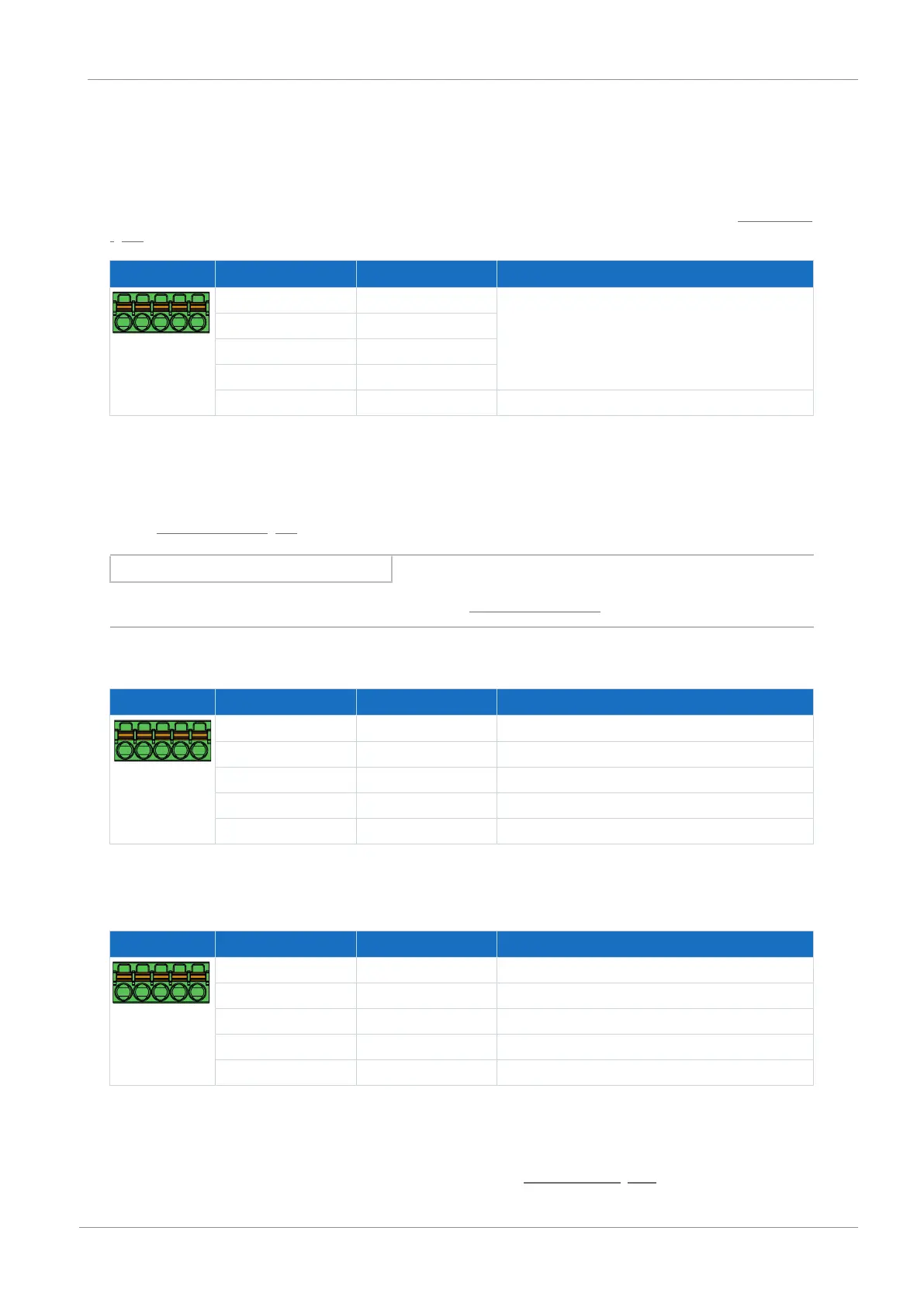
Terminal Pin Designation Function
5|4|3|2|1
1 BE6 Binary inputs
2 BE7
3 BE8
4 BE9
5 DGND Reference ground; not bridged with X101, pin 5
Tab. 93: X103 connection description for binary signals
X103 for encoders
If you would like to use X103 as an encoder connection, note the technical data of the evaluable encoders at X103; see the
chapter X103 for encoders [}46].
Information
Note that a master encoder must be connected to X101 during synchronous operation.
Single-ended HTL incremental encoders
Terminal Pin Designation Function
5|4|3|2|1
1 BE6 —
2 BE7 N channel
3 BE8 A channel
4 BE9 B channel
5 DGND Reference ground; not bridged with X101, pin 5
Tab. 94: X103 connection description for single-ended HTL incremental signals, axis B
Single-ended HTL pulse train
Terminal Pin Designation Function
5|4|3|2|1
1 BE6 —
2 BE7 —
3 BE8 Frequency
4 BE9 Direction
5 DGND Reference ground; not bridged with X101, pin 5
Tab. 95: X103 connection description for single-ended HTL pulse/direction signals, axis B
Connecting wiring
For connecting wiring, observe the terminal specifications in the chapter FMC 1,5 -ST-3,5 [}189].

 Loading...


