12 | Diagnostics STOBER
130
05/2019 | ID 442790.01
12.1.3 Drive controller state
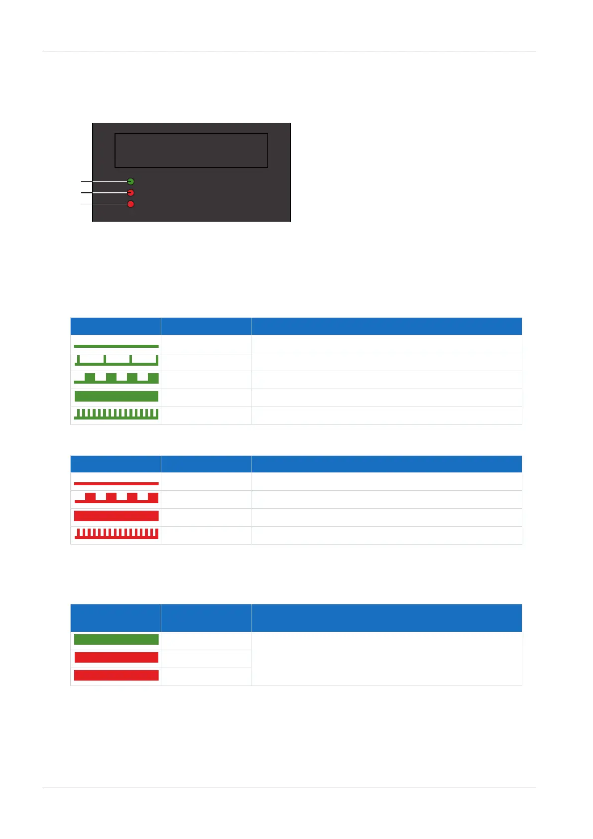
3 LEDs on the front of the device provide information about the state of the drive controller.
Fig.26: LEDs for the state of the drive controller
1 Green: Run
2 Red: Error in axis controller A
3 Red: Error in axis controller B (only for double-axis controllers)
Green LED Behavior Description
Off No supply voltage or axis controller A or B faulty
Single blink STO active
Flashing At least 1 axis controller ready to switch on; no axis controller faulty
On At least 1 axis controller enabled; no axis controller faulty
Rapid flashing Data is written to internal memory and the SD card
Tab. 137: Meaning of the green LED (run)
Red LED Behavior Description
Off No error
Flashing Warning
On Fault
Rapid flashing No configuration active
Tab. 138: Meaning of the red LEDs (error)
Pattern when starting the drive controller
LEDs:
Green/Red/Red
Behavior Description
On Short phase while the firmware starts up
On
On
Tab. 139: States of the LEDS when starting the drive controller

 Loading...


